The performance of a formation tray pressurizing device is set not by the pressing force but by the stiffness of the load path through which the pressing reaction returns via the side wall to the base plate. KR102088762B1 (applicant LG Chem, now LG Energy Solution; filed and prioritized 2017-04-18; granted 2020-03-13) claims a tray that presses a stack of storage plates from one end so that battery cells are fixed without play. Claim 1 requires that the distance D between the pressing plate and the inner face of the first side wall be set equal to the total stack thickness T and fixed at that position. This post reviews, from a mechanical standpoint, what must be controlled for the “D = T” condition to hold in a manufactured part.
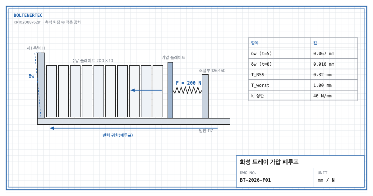
1. Problem definition — does D = T on the drawing hold in the built part?
Several storage plates are stacked, and each has a machining tolerance on thickness. If the pressing plate sits at a fixed position, a thick stack is over-pressed and a thin stack leaves play. If the side wall that carries the reaction bends, D grows again. So which governs the play: side-wall stiffness or stack tolerance?
For this reason the claim also recites a pressure adjusting unit. The specification describes an adjusting screw bolt and a spring member that set the pressing force. The spring rate and thread size are not stated in the specification.
2. Kinematic analysis — a closed load loop
| Component (reference numeral) | Mechanical role | Position in load path |
|---|---|---|
| Pressing plates 121·122 | Press one end of the stack | Point of action |
| Storage plates 200 | Hold cells; compression member along stack | Compression transfer |
| First side wall 111 | Support face opposite the stack | Reaction point (bending member) |
| Base plate 117 | Fixed end of the side wall | Loop return |
| Adjusting bolt 126, spring 160 | Force setting, tolerance absorption | Series elastic element |
The pressing force never leaves the tray. It is a closed loop from the pressing unit through the stack, the first side wall and the base plate back to the pressing-unit support. The softest member in the loop creates the play. The side wall can be treated as a cantilever fixed to the base plate.
3. Calculation — side-wall deflection vs. stack tolerance
Design assumptions (to be reconfirmed by field measurement): pressing force $F$ = 200 N, load height on side wall $a$ = 60 mm, wall width $b$ = 300 mm, thickness $t$ = 5 mm, material Al 6061-T6 (elastic modulus 68,900 MPa, yield strength 276 MPa, ASM Handbook nominal values).
$$I=\frac{b t^{3}}{12}=\frac{300\times 5^{3}}{12}=3{,}125\ \mathrm{mm^{4}}$$
$$\delta_w=\frac{F a^{3}}{3 E I}=\frac{200\times 60^{3}}{3\times 68{,}900\times 3{,}125}=0.067\ \mathrm{mm}$$
Here $I$ is the second moment of area of the wall (mm⁴) and $\delta_w$ is the deflection at the load point (mm). A 0.067 mm wall deflection increases D by the same amount.
$$\sigma=\frac{F a}{b t^{2}/6}=\frac{12{,}000}{1{,}250}=9.6\ \mathrm{MPa},\qquad SF_{1}=\frac{276}{9.6}=28.8$$
The strength margin is 28.8. Strength cannot decide the wall thickness.
With an allowable play of 0.05 mm (assumed), the stiffness safety factor is:
$$SF_{2}=\frac{\delta_{allow}}{\delta_w}=\frac{0.05}{0.067}=0.75$$
A 5 mm wall is insufficient. At 8 mm, $I$ = 12,800 mm⁴, $\delta_w$ = 0.016 mm and $SF_2$ = 3.06. A 1.6× thickness cuts deflection to 1/4 because of the $t^3$ dependence.
The stack tolerance, however, is larger. With 10 storage plates at ±0.1 mm each (assumed):
$$T_{worst}=n\,t_p=10\times 0.1=1.0\ \mathrm{mm},\qquad T_{RSS}=\sqrt{n}\,t_p=0.32\ \mathrm{mm}$$
A stack tolerance of 0.32–1.0 mm is more than 20 times the 0.016 mm wall deflection. Fixed-position pressing alone cannot keep D = T. That is the mechanical reason the claim also recites the pressure adjusting unit.
To keep force variation within ±20% while the spring absorbs 1.0 mm of tolerance, the spring rate must satisfy:
$$k \le \frac{0.2F}{\Delta T_{worst}}=\frac{40}{1.0}=40\ \mathrm{N/mm}$$
Selecting $k$ = 20 N/mm with 10 mm initial compression keeps the variation within ±10% even at worst-case tolerance.
4. Shop-notes
- Ribs rather than thickness. A 5 mm plate with two vertical ribs gives the same stiffness as an 8 mm plate without added mass. Machinability: for aluminum, one-piece machining of the ribs holds flatness better than welding. Specify 0.05 mm flatness on the inner face of the first side wall.
- Control storage-plate thickness first. Reducing ±0.1 mm per plate to ±0.03 mm brings the RSS stack tolerance to 0.095 mm. This requires grinding or precision molding; weigh the cost against the reduced spring adjustment range.
- Alternative mechanism — pressing both ends of the stack. The claim covers pressing one or both ends. Pressing both ends keeps the stack centered. Not adopted because: two pressing units enlarge the tray envelope and mass and widen the rack pitch. A one-end spring is enough to absorb tolerance.
- Safety. Spring energy remains while the adjusting bolt is operated. The work standard must specify releasing spring compression before disassembly (pinch prevention).
5. Design checklist
- Was the deflection of each member in the loop (pressing unit → stack → side wall → base) summed?
- Is a side-wall stiffness factor $SF_2$ ≥ 2 secured?
- Was the stack tolerance calculated both as worst case and RSS?
- Was the spring rate back-calculated from the allowable force variation?
- Are the flatness of the first side wall and the squareness of the base specified on the drawing?
Items requiring confirmation
- Pressing force, spring rate, tray material and dimensions are not stated in the specification. All figures in this post are design-review assumptions.
- The wording of claim 1 should be reconfirmed against the original publication (KIPRIS).
One-line summary: The stack tolerance of 0.32 mm is 20 times the 0.016 mm side-wall deflection, so the D = T condition must be held by the spring adjusting unit, not by wall thickness.
Source: KR102088762B1, “Tray having pressurizing apparatus for accommodating battery cell”, claim 1 and specification (pressing unit and pressure adjusting unit).