In spindle-type reel handoff from an AGV, the alignment tolerance is governed not by spindle deflection but by the vehicle’s stop-position error, and the lead-in width of the shape coupling that absorbs it is the real design specification. EP4119475B1 (proprietor Manz Italy S.r.l.; priority IT 2021-07-12; filed 2022-07-06; grant mentioned 2024-09-04) claims a system in which a support spindle carried by a vehicle transfers a reel to the feeding unit of an automatic machine, while a gripper carried by the vehicle grips the initial flap of the reel and keeps it tensioned along the unwinding path. This post breaks down the alignment error budget at the moment of handoff.
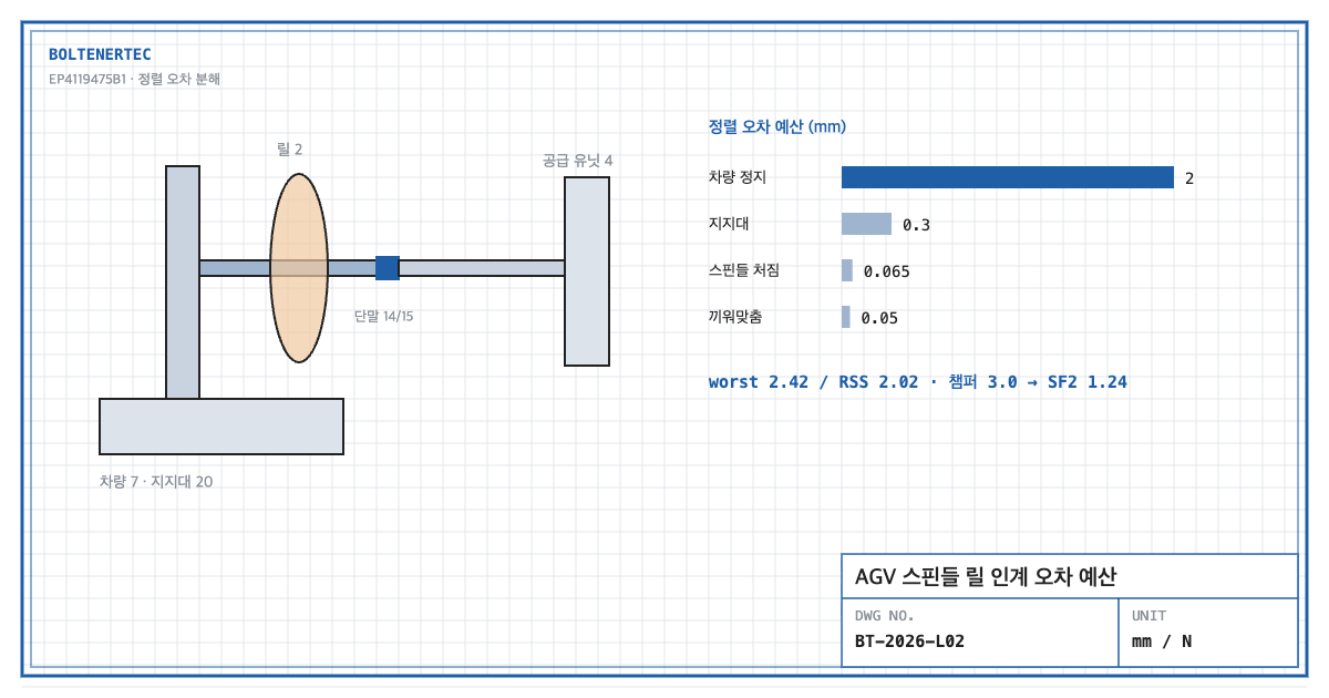
1. Problem definition — what makes two spindles one axis?
According to [0054] and [0055], shaped terminal 14 of vehicle spindle 8 couples by shape with complementary terminal 15 of feeding-unit spindle 5. The reel is pushed across this coupling onto the feeding unit. If the two spindles are not coaxial, the reel core catches on the step at the coupling. So what should secure coaxiality: spindle stiffness, vehicle positioning accuracy, or coupling geometry?
2. Kinematic analysis — claim elements
| Element | Claim 1 feature | Mechanical interpretation |
|---|---|---|
| E1 | Vehicle 7 carrying a reel from storage/receiving station to change station | Source of position error |
| E2 | Support spindle 8 on the vehicle, transferring the reel to feeding unit 4 | Cantilever + shape coupling |
| E3 | Gripping member 11 on the vehicle, gripping and tensioning initial flap 2a | Web tension aid |
[0035] describes the vehicle as a conveyor trolley with base body 10, wheels 21 and a vertical support upright 20. The spindle is a cantilever hung from the upright.
3. Calculation — alignment error budget
Design assumptions (to be reconfirmed by field measurement): reel mass 80 kg ($P$ = 784.8 N), distance from spindle fixed end to reel center $a$ = 250 mm, spindle S45C solid Ø50 (elastic modulus 205,000 MPa, yield 345 MPa), vehicle stop-position error ±2.0 mm, error from upright tilt 0.3 mm, terminal fit clearance 0.05 mm.
$$\delta_s=\frac{P a^{3}}{3EI}=\frac{784.8\times 250^{3}}{3\times 205{,}000\times 3.07\times 10^{5}}=0.065\ \mathrm{mm}$$
$$\sigma=\frac{P a}{\pi d^{3}/32}=16.0\ \mathrm{MPa},\qquad SF_{1}=\frac{345}{16.0}=21.6$$
Spindle deflection is 0.065 mm and the strength margin is 21.6. The deflection slope is 0.022°, so angular error at the coupling is also negligible.
$$e_{worst}=2.0+0.065+0.3+0.05=2.42\ \mathrm{mm},\qquad e_{RSS}=\sqrt{2.0^{2}+0.065^{2}+0.3^{2}+0.05^{2}}=2.02\ \mathrm{mm}$$
On an RSS basis, 98% of the error variance comes from vehicle stop position. A thicker spindle does not improve alignment.
With a coupling lead-in chamfer width $c$ of 3.0 mm (assumed):
$$SF_{2}=\frac{c}{e_{worst}}=\frac{3.0}{2.42}=1.24$$
The worst-case margin of 1.24 is thin. Widening the chamfer to 4.0 mm gives 1.66. Alternatively, mechanical locating (docking pins) at the change station that reduces vehicle error to 0.5 mm gives a worst-case error of 0.92 mm and a margin of 3.3 on a 3.0 mm chamfer.
4. Shop-notes
- Docking pins before chamfers. A wider chamfer can increase play after coupling. Tapered docking pins on the station floor or machine frame constrain the vehicle mechanically and reduce the error source directly.
- Machinability. Machine shaped terminal 14 and complementary terminal 15 as a matched pair and engrave the pair number. Turn the spindle integral with its terminal to hold 0.02 mm concentricity.
- Alternative mechanism — floating spindle on the feeding unit. A radially floating feeding-unit spindle accepts the error. Not adopted because: reel rotation stability during operation drops, and shaft stiffness, a boundary condition for unwind tension control, is lowered.
- Safety. The space between the flap gripper and rollers is a draw-in hazard. Stop the handoff if a worker is detected entering the protected zone.
5. Design checklist
- Was alignment error broken down into vehicle, upright, spindle and fit items?
- Were both worst case and RSS calculated?
- Is $SF_2$ ≥ 1.5 secured on coupling lead-in width?
- Has mechanical locating at the change station been decided?
- Is draw-in protection at the flap gripper included?
Items requiring confirmation
- The specification states no dimensions, masses or speeds (checked in the full EPO publication). All figures here are assumptions.
- Vehicle stop-position error should be reconfirmed from the AGV specification and field measurement.
One-line summary: Of the 2.42 mm reel-handoff alignment error, spindle deflection is only 0.065 mm, so design resources belong in vehicle locating and coupling lead-in width, not spindle stiffness.
Source: EP4119475B1, “System for replacing a reel of material for the production of electrical energy storage devices and related method”, claim 1 and specification [0035], [0054], [0055].