Bearing life calculation1 turns a load into the number of revolutions that 90% of identical bearings survive without fatigue damage. Here I run that formula on a single guide roll carrying an electrode web.
- Rating life comes from the catalogue load rating divided by the actual load, cubed for a ball bearing. The unit is millions of revolutions.
- Double the load and the life does not halve. It drops to one eighth.
- With a published electrode tension of 110 N and an SKF 6205 bearing, a guide roll bearing rates at more than 100 million hours (roll diameter assumed).
- I would not choose the bearing on that number. ISO 281 leaves wear, corrosion and electrical erosion out of the calculation.
An electrode line runs roll-to-roll2. The coated web leaves the coater, passes the roll press and the slitter, and is wound up again at the winder. Between those machines, rolls that turn the web and set its height are called guide rolls3. Most have no motor. The moving web drags them round.
Each end of a guide roll sits in a bearing, and the bearing turns for as long as the roll does. I treat bearing selection as a basic calculation of the mechanical design job. Statics, the life equation from machine elements, and one number from a maker’s catalogue all meet in it.
Give 100 people the same pair of shoes, made in the same factory on the same day, and send them along the same route. Some soles crack early, some never do. The distance walked when the tenth pair fails is what a bearing catalogue calls rating life.
Shoes usually end by wearing thin. The bearing life equation counts something else: the raceway, rolled over by balls millions of times, tires under repeated stress and sheds flakes. Only that fatigue flaking4 is in the count.
Figure 1 puts the same idea into 100 bearings. The ten in red are the share that fails before reaching rating life.
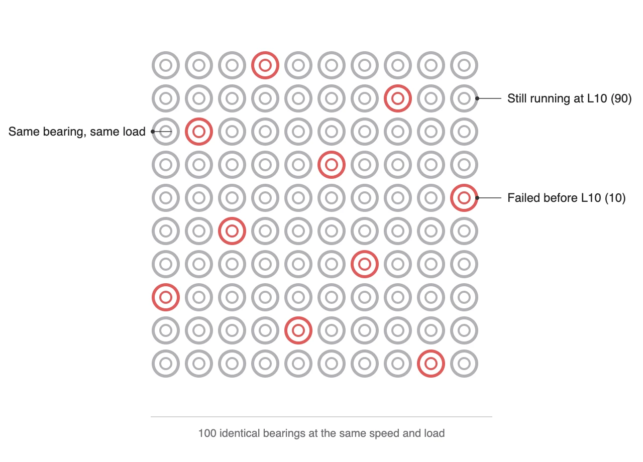
That is where the symbol L10 comes from. The Japanese bearing maker JTEKT describes it as the life at 90% reliability and notes that the other 10% may fail sooner. Read it as a statement about a population. It does not tell you when one particular bearing will stop.
Two values go into the calculation: the basic dynamic load rating C5 printed in the catalogue, and the equivalent load P6 the bearing actually carries. Divide C by P, raise it to the power 3 for a ball bearing or 10/3 for a roller bearing, and the result is rating life in millions of revolutions. The method grew out of work done at SKF in 1947 by Lundberg and Palmgren, and ISO 2817 now sets it out.
The factor of eight in the middle card is the exponent at work. Twice the load gives two cubed, one eighth of the life. Run it the other way and a modest load reduction buys a lot of life. That cube is also why going up one bearing size pays off on a heavily loaded roll.
How much load does one roll put on its bearings?
A guide roll bearing’s load starts with the pull on the electrode web, the web tension8. A 2023 paper from the Karlsruhe Institute of Technology (KIT) lists the test settings of its lab calender: 110 N at the tension unit and 60 N each at the unwinder and rewinder. The machine’s web speed is adjustable from 1 to 30 m/min. A 2024 paper from Shanghai Jiao Tong University states that production lines roll at up to 100 m/min.
How hard that tension presses on the roll depends on how far the web wraps around it, the wrap angle9. With a 180° wrap, the incoming and outgoing spans pull the roll the same way, so the roll sees twice the tension. With 90°, the two spans meet at a right angle and the roll sees about 1.41 times the tension.
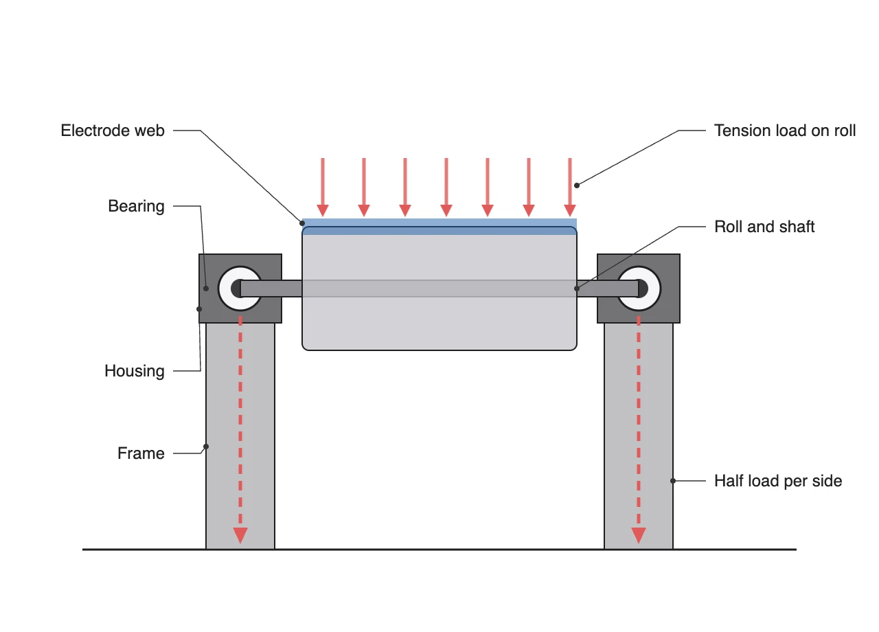
In Figure 2 the combined force runs through the roll body into the shaft, and each end bearing takes half. From the bearings it passes through the housings and the frame into the floor. Designers trace this route as the load path10. I draw it even for a single bearing, because until I know where the force comes from and where it leaves, I have no number to put in for P.
I paired the two tensions from the KIT paper with the two wrap angles. The bearing is an SKF 6205-2ZNR deep groove ball bearing: 25 mm bore, 52 mm outside diameter, basic dynamic load rating 14.8 kN. No public source gives the roll diameter, so I assumed 100 mm. That puts the roll at about 95.5 r/min at 30 m/min and about 318 r/min at 100 m/min.
| Tension | Wrap | Load per bearing | Rating life | 30 m/min | 100 m/min |
|---|---|---|---|---|---|
| 60 N | 90° | 42.4 N | 42.45 million Mrev | ≈7.4 billion h | ≈2.2 billion h |
| 60 N | 180° | 60.0 N | 15.01 million Mrev | ≈2.6 billion h | ≈790 million h |
| 110 N | 90° | 77.8 N | 6.89 million Mrev | ≈1.2 billion h | ≈360 million h |
| 110 N | 180° | 110.0 N | 2.44 million Mrev | ≈430 million h | ≈128 million h |
Even the harshest row gives about 127.5 million hours, more than 14,000 years of round-the-clock running. The table leaves out the roll’s own weight, so the real load is higher. If the roll weighed as much as the tension resultant, the load would double and life would fall to one eighth, about 16 million hours (estimate). Roll weight is a value to confirm by measurement on site.
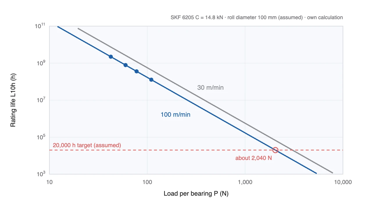
Both lines in Figure 3 share one slope: on log scales, one decade up in load is three decades down in life. Set a target of 20,000 hours (assumed) and read the 100 m/min line backwards, and this bearing could carry about 2,040 N each and still reach it. That is roughly 18.5 times the 110 N in the table.
Why do bearings stop when the math says 100 million hours?
A calculated life of 100 million hours means the bearing will last that long.
ISO 281 states in its scope that it does not cover the influence of wear, corrosion or electrical erosion on bearing life.
The life equation counts the time until a raceway flakes from fatigue under clean lubrication. Surface wear, corrosion from moisture and chemicals, and electrical erosion11, where current pits the raceway, are outside it. On a lightly loaded spot like a guide roll, my judgment is that one of those three arrives long before fatigue does.
Raising the reliability target does not change that. The reliability factor a112 in the Autodesk Inventor help is 1 at 90% and 0.21 at 99%. At 99% the 127.5 million hours become about 26.8 million, still far beyond the life of the machine.
Too little load is a problem of its own. SKF’s deep groove ball bearing catalogue warns that at speed, the inertia of balls and cage and friction in the lubricant can upset rolling and cause damaging sliding between balls and raceways. Hence its advice to check a minimum load13. Upsizing a bearing to chase life keeps the real load where it was while the rating grows, which moves it further from that minimum.
So when I pick a guide roll bearing, four things come before the life equation: the shield or seal that keeps dirt out, the lubrication, the minimum load, and the fits on shaft and housing. Slitting electrodes makes dust, so I start from a type shielded on both sides, like the 6205-2ZNR in this calculation. The side where the web runs onto the roll is an in-running nip that can draw a hand in, so the guard position is laid out together with the bearing housings.
Across the whole plant, guide rolls cluster in the electrode stage, the blue block in Figure 4.
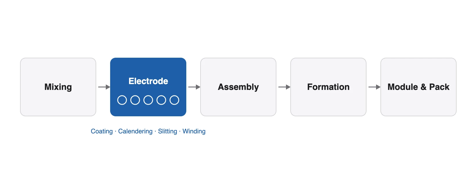
By load, electrode rolls fall into three groups. The two rolls of the roll press squeeze the electrode to thickness, so life and deflection calculations set their size. In the winder the torque changes with roll diameter. Guide rolls carry the lightest loads of the three. On a roll press, rating life sizes the bearing. On a guide roll, minimum load and sealing decide the type.
Where this calculation sits in the design job
Even one bearing passes through four tools, and my own work runs down this table from top to bottom.
| Task | Tool | Output |
|---|---|---|
| Split tension and wrap into bearing loads and check life | Python calculation tool | Calculation sheet (inputs, formulas, results) |
| Place bearings and housings in 3D and recheck life with catalogue data | Autodesk Inventor | 3D model, assembly drawing |
| Detail shaft and housing parts with fit tolerances | AutoCAD, MechClick | 2D part drawings |
| Automate repetitive drafting | AutoLISP | Scripts |
Inventor’s Bearing Generator14 returns a life using the ISO 281 method. I still run the same numbers through my Python tool. The program cannot tell me whether the load I typed in is right. Misread the wrap angle, enter half the load, and the life comes out eight times too high. Raising an alarm from a rotation signal belongs to the PLC side; mechanical design hands over the sensor position and the allowable load.
For a mechanical engineering student heading into this field, the first row is closest to the textbook: force resultants from statics, the life equation from machine element design. If an interviewer asks about bearing life, be ready to say what happens to life when the load doubles before reciting the formula. The full design-to-FAT cycle is covered in battery equipment mechanical design, and the companies building electrode machines are grouped by process in the electrode equipment maker map.
One step further, for engineers
The roll resultant and the load per bearing come from the wrap angle.
$$R = 2T\sin\frac{\theta}{2},\qquad P = \frac{R}{2}$$
$R$ is the resultant on the roll (N), $T$ the web tension (N), $\theta$ the wrap angle (°), and $P$ the equivalent load per bearing (N). The load is treated as purely radial; axial load and roll weight are left out.
$$L_{10} = \left(\frac{C}{P}\right)^{p},\qquad L_{10h} = \frac{10^{6}}{60\,n}\,L_{10},\qquad n = \frac{1000\,v}{\pi D}$$
$L_{10}$ is rating life (millions of revolutions), $C$ the basic dynamic load rating (N), $p$ = 3 for ball and 10/3 for roller bearings, $L_{10h}$ rating life (h), $n$ speed (r/min), $v$ web speed (m/min), and $D$ roll diameter (mm). With $C=14{,}800$ N, $P=110$ N, $v=100$ m/min and $D=100$ mm (assumed), $n\approx318.3$ r/min and $L_{10h}\approx1.28\times10^{8}$ h.
I check two safety margins. First, the static safety factor $s_0 = C_0/P_0 = 7{,}800/110 \approx 70.9$. Second, the life margin against a 20,000 h target (assumed) is about 6,400 times. Both are large, so here minimum load and sealing govern the selection, not strength or fatigue. Roll weight and axial load need confirmation by measurement on site.
Machinability note: bore the bearing seats of both housings in one setup so they come out coaxial. Housings machined separately twist the shaft at assembly and put a moment on the bearings. Take fit tolerances from the bearing maker’s recommended tables. An alternative is a dead shaft with the bearings inside the roll. It saves length, but inspecting or replacing a bearing means taking the whole roll out, so I did not use it as the base design here.
Further reading: Bearing Life Calculator: ISO 281 in PySide6
Before a guide roll bearing drawing leaves my desk, I check five items.
- Is the load per bearing written in N, from tension and wrap angle?
- Is the speed worked out from web speed and roll diameter?
- If rating life comes out very large, has the minimum load been checked?
- Is the shield or seal type chosen against dust and moisture?
- Is the nip guard drawn together with the housing layout?
Glossary
- Bearing life calculation: working out how many revolutions a bearing can make before fatigue damage, from its load and its load rating. ↩
- Roll-to-roll (R2R): continuous production in which a long web is unwound from a roll, processed, and wound onto a roll again. ↩
- Guide roll: a roll that changes the direction or height of the web on its way to the next machine. An undriven one that simply follows the web is also called an idler roll. ↩
- Flaking: damage in which the surface of a raceway or rolling element comes away in flakes after repeated loading. ↩
- Basic dynamic load rating (C): the load at which rating life equals one million revolutions. Each bearing’s value is listed in the maker’s catalogue. ↩
- Equivalent load (P): radial and axial loads combined into a single load that gives the same life. ↩
- ISO 281: the international standard for dynamic load ratings and rating life of rolling bearings. The current edition dates from 2007. ↩
- Web tension: the lengthwise pull on the web. Too little and the web sags; too much and it stretches or wrinkles. ↩
- Wrap angle: the arc of the roll in contact with the web, measured from the roll centre. ↩
- Load path: the route a force takes from where it starts, through each part in turn, to the ground. ↩
- Electrical erosion: damage when current passes through a bearing and sparks between raceway and rolling element melt and pit the surface. ↩
- Reliability factor (a1): the multiplier applied to rating life for a reliability other than 90%. It gets smaller as reliability goes up. ↩
- Minimum load: the smallest load a bearing needs so its balls roll instead of slide. ↩
- Bearing Generator: a function inside the 3D CAD program Autodesk Inventor that inserts bearings and calculates their load and life. ↩
Sources
- ISO 281:2007, Rolling bearings: Dynamic load ratings and rating life, edition 2 (2007-02), scope, iso.org
- SKF Group, Selection of bearing size: using the life equations (GC6000-2-3), pp. 4–5, skf.com
- SKF, 6205-2ZNR product data sheet (bore 25 mm, outside diameter 52 mm, C 14.8 kN, C0 7.8 kN), generated from skf.com
- SKF, Deep groove ball bearings catalogue, Minimum load, p. 38, SKF catalogue PDF
- E. Ioannides, G. Bergling, A. Gabelli, “The SKF formula for rolling bearing life”, SKF Evolution, 2001-02-16, evolution.skf.com
- JTEKT, Bearing knowledge 5-2-1 Basic dynamic load rating C, jtekt.co.jp
- Autodesk, Inventor 2026 Help, Bearing Calculation Formulas (reliability factor a1 table), help.autodesk.com
- A.-K. Wurba et al., Methodology for the characterization and understanding of longitudinal wrinkling during calendering of lithium-ion and sodium-ion battery electrodes, Procedia CIRP 120 (2023) 314–319, sections 2.1 and 2.4, KIT
- Z. Fu, Z. Xu, L. Peng, The effect of web tension on calendering wrinkles and corrugations of coated foils, Materials Research Proceedings 44 (2024) 305–319, introduction, doi.org
This article is for understanding the industry and its technology and is not a recommendation to buy or sell any security.