Transfer robot gripper clamping pressure is the compressive force per unit area that the end effector of a multi-joint robot picking up and moving a pouch cell applies to the cell surface. On September 2, J’s Robotics disclosed that it signed a KRW 33.3 billion secondary battery manufacturing robotics automation equipment supply contract. The contract counterparty and detailed specifications are undisclosed for trade-secret protection reasons (undisclosed). Unlike prismatic or cylindrical cells, pouch cells have an aluminum laminate film exterior, making them vulnerable to local compression. If gripper clamping pressure is excessive, indentation at the pouch sealing area or internal electrode displacement occurs; if it is too low, slip during transfer causes drop accidents. What criterion to use in setting the clamping pressure is the key question of mechanical design.
Kinematic Analysis: Parallel Jaws vs. Multi-Point Support
Grippers are divided into 2-point parallel jaw and 3-or-more-point multi-point support types. Parallel jaws have a simple structure, but the entire cell weight is concentrated on a narrow contact surface, raising local pressure. Multi-point support widens the contact area and disperses pressure, but the number of actuators and alignment tolerance management points increases with the number of jaws. Since the clamping force must withstand the acceleration/deceleration loads generated during transfer as well, calculating the minimum clamping force reflecting the static friction coefficient and safety factor comes first.
Calculation and Formula Verification
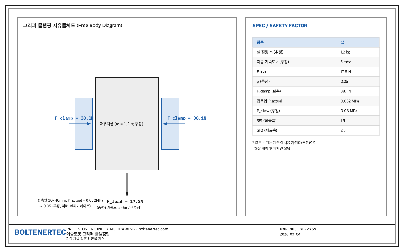
The mass $m$ of one large pouch cell is assumed to be 1.2 kg (estimate; basis: typical weight of a large 60 Ah-class EV pouch cell). The acceleration/deceleration $a$ during the robot transfer segment is assumed to be 5 m/s² (estimate; basis: typical operating profile of a vertical articulated transfer robot).
$$F_{load} = m \times (g + a) = 1.2 \times (9.81 + 5) = 17.8\ \text{N}$$
To support this load by friction alone, a primary safety factor of $SF_1 = 1.5$ is applied, based on 2 gripper jaw faces and a pad-to-film friction coefficient of $\mu = 0.35$ (estimate; typical value for rubber pad–aluminum laminate contact).
$$F_{clamp} = \frac{F_{load} \times SF_1}{\mu \times n} = \frac{17.8 \times 1.5}{0.35 \times 2} = 38.1\ \text{N (per side)}$$
If the jaw contact area is taken as 30 mm × 40 mm (estimate; rubber pad specification) = 1200 mm², the actual contact pressure is as follows. This has practical significance in that the lower this value, the lower the risk of indentation at the pouch sealing area.
$$P_{actual} = \frac{F_{clamp}}{A} = \frac{38.1}{1200} = 0.032\ \text{MPa}$$
Assuming the pouch cell surface allowable local pressure $P_{allow}$ is 0.08 MPa (estimate; basis: typical value from pouch cell handling guides, re-confirmation required after field measurement), the secondary safety factor is as follows.
$$SF_2 = \frac{P_{allow}}{P_{actual}} = \frac{0.08}{0.032} = 2.5$$
With $SF_1 = 1.5$ and $SF_2 = 2.5$, both dual safety-factor criteria (typical minimum 1.2–1.5) are satisfied. The key point of this calculation is that the load-side and material-side safety factors were verified separately.
Practical Application (Shop-notes)
Vacuum suction pad method could be reviewed as an alternative mechanism. It can lower local pressure further, but if there is folding or minute curvature at the sealing area of the pouch film exterior, suction force drops sharply, making it less stable in sections with large cell surface flatness deviation, such as early mass-production lines. It is not adopted in this design. As a machinability note, the jaw surface rubber pad requires polyurethane (Shore A 40–50) injection molding followed by contact-surface rounding (R) machining, and a regular replacement jig matched to the pad wear cycle (estimated at approximately 200,000 cycles) must be designed together so that machining/maintenance burden does not grow.
- Measure gripper jaw contact pressure with a load cell and compare against the calculated value
- Recalculate reflecting measured robot acceleration/deceleration profile
- Confirm pouch cell allowable local pressure per manufacturer specification (currently unconfirmed)
- Establish standard rubber pad wear replacement cycle
One-Line Summary: A transfer robot gripper must secure $SF_1$ 1.5 and $SF_2$ 2.5 or higher at a contact pressure level of 0.032 MPa to safely transfer pouch cells without indentation.