US20240429495A1 claims a structure that arranges the stacked layers inside a prismatic battery can in an inverted-U shape.
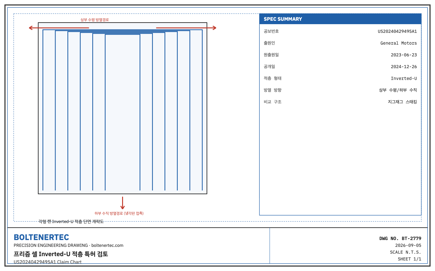
Patent Bibliographic Information
US20240429495A1 (“Prismatic Inverted-U Battery Stack Geometry”), Applicant: General Motors, Original Filing Date: 2023-06-23, Publication Date: 2024-12-26 (Publication No. 20240429495, confirmed via USPTO/Justia Patents, Google Patents). It claims a structure in which the stacked layers inside a prismatic battery can are folded and arranged in an inverted-U shape.
Patent Claim Elements vs. Target Equipment Comparison (Claim Chart)
| Claim Element | Patent Disclosure | Corresponding Structure in Typical Prismatic Cell Stacking/Winding Equipment | Correspondence |
|---|---|---|---|
| Multilayer stacked layers inside prismatic can | Continuous sheet arranged folded into inverted-U shape | Zigzag stacking or winding-then-pressing method used in parallel | Partial correspondence (differing stack geometry) |
| Upper horizontal heat-transfer path | Enhanced horizontal-direction heat dissipation at can top | Top is typically used as space for electrode tab extraction | Different structure (design-around potential) |
| Lower vertical heat-transfer path | Enhanced vertical-direction heat dissipation near can bottom | Bottom cold-plate contact method is common | Partial correspondence |
| Folding process | Folding process shaping the sheet into an inverted-U | Similar function to the folding unit in zigzag stacking equipment | Partial correspondence (forming trajectory may differ) |
Practical Significance
The inverted-U stacking geometry is an idea for separating the heat-dissipation paths at the top and bottom of the can, and it is difficult to directly use the folding-unit trajectory of existing zigzag stacking equipment as-is. Redesigning the folding head’s reciprocating trajectory to match inverted-U forming leaves room to design around part of this claim element (this is not a conclusion on infringement, and claim scope interpretation requires separate review), but the design concept itself of separating the upper and lower heat-transfer paths is worth referencing when re-reviewing pack cold-plate placement. To give the can top a heat-dissipation function, interference with the electrode-tab extraction structure that occupies the top space must also be reviewed.
One-Line Summary: The inverted-U stack’s core is separating the can’s upper/lower heat-dissipation paths, and redesigning the folding trajectory leaves room to design around part of the claim (final judgment on patent validity requires separate review).