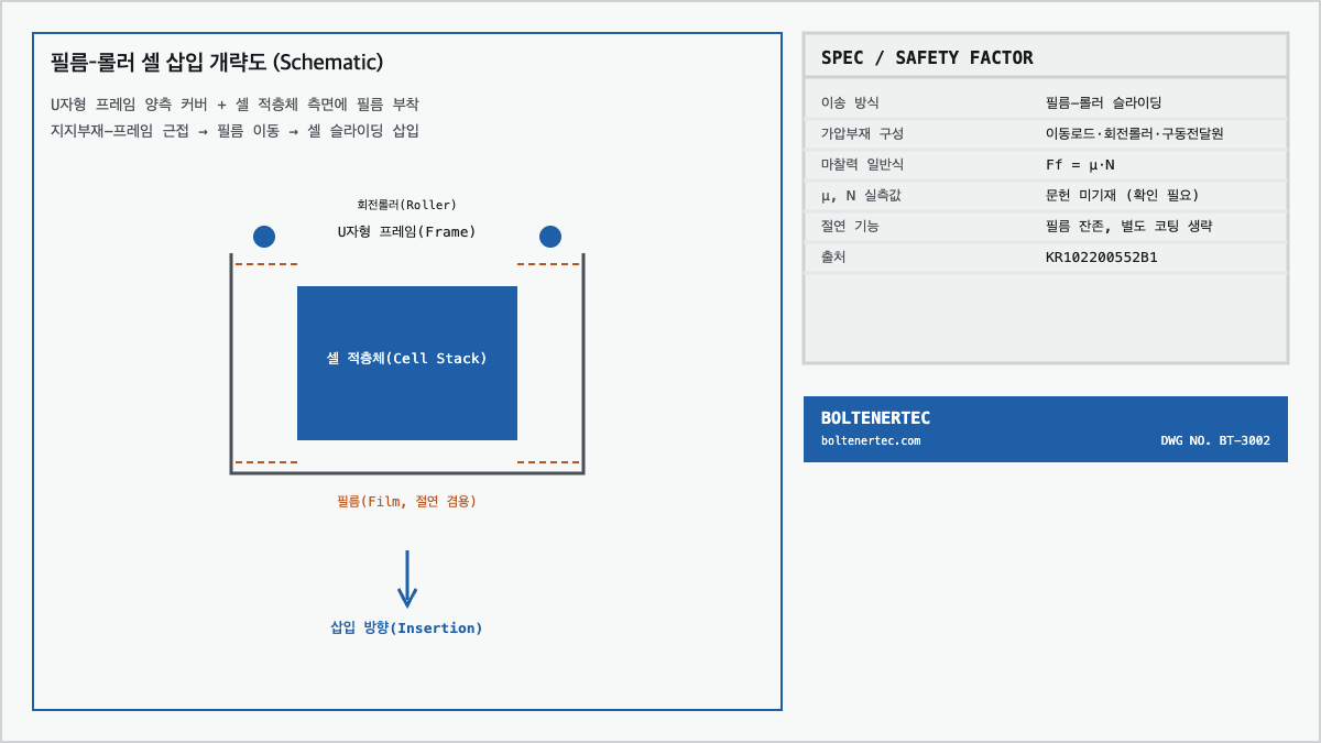
When inserting a pouch cell stack into a logistics-process carrier frame, contact-surface damage and insulation failure tend to occur simultaneously. KR102200552B1 discloses a structure in which one side of a film is attached to both side covers of the frame and the other side of the film is attached to the side of the cell stack, after which a rotating roller contacts the film to guide the cell stack via film sliding, inserting it into the frame (KR102200552B1, specification).
Problem Definition
During transfer between the formation and logistics processes, when inserting a cell stack into a tray or carrier frame, direct contact between the frame side and the cell surface can cause damage and insulation failure. KR102200552B1 presents a structure that resolves this issue by using a film as an intermediary between the frame and the cell (KR102200552B1, specification).
Kinematic Analysis
The pressing device consists of three elements: a moving rod, a rotating roller, and a drive-force transmission source (motor or cylinder). The moving rod is arranged to move to a height corresponding to the cell stack height, and the rotating roller rotates while contacting the film, sliding-transferring the cell stack. The film is an insulating film that remains inside the frame, replacing a separate insulation coating process (KR102200552B1, specification).
Formula Verification
The friction force at the film-cell contact surface can be approximated using the general Coulomb friction equation.
$$F_f = \mu \times N$$
$F_f$: friction force (N), $\mu$: coefficient of friction between film and cell surface (dimensionless), $N$: normal force applied by the rotating roller to the film (N)
The specification does not state measured values for $\mu$ or $N$ (not stated in the literature, confirmation required). Therefore, this equation is limited to presenting a design-review relational expression; quantitative friction-force calculation requires separate in-house measurement.
Dual Safety-Factor Verification
- 1st — Film tensile safety factor: the film material, thickness, and tensile strength are not stated in the specification; confirmation required.
- 2nd — Cell surface damage safety factor: the rotating roller’s pressing force $N$ is not stated, making contact-pressure calculation impossible; confirmation required.
- Conclusion — Since the values required to calculate both safety factors are absent from the literature, quantitative verification is reserved; this review is limited to presenting the friction-force relational expression.
Shop-notes
- The flatness of the frame side-cover film-attachment surface directly affects cell sliding resistance, so management within 0.1mm is recommended. (Machinability: flatness is easily secured by separately polishing/finishing only the film-attachment surface after milling the aluminum plate)
- If a cylinder is selected as the drive-force transmission source, pressing-force adjustment is easier than with a motor, but repeat precision is lower than a servo motor; for repeated insertion processes, a servo motor + load-cell feedback combination should be reviewed first.
- Until measured data on film tensile strength and friction coefficient are secured, insertion speed should be set conservatively to manage film-rupture risk.
One-line summary: The logistics-process cell insertion uses a moving-rod, rotating-roller, and drive-transmission-source structure to insert the cell via film-mediated sliding, but key values for safety-factor calculation such as friction coefficient and tensile strength are not stated in the literature and require confirmation.