The precision limit of inline weld-depth measurement is set not by optical resolution but by the mount stiffness of the processing head, which serves as the measurement reference plane.
Problem Definition
LG Energy Solution has applied non-destructive 100% laser-weld inspection to a US ESS battery module assembly (BMA) line. The equipment has been supplied by IPG Photonics in over 80 units since last year, and is used in the process of joining pouch-type LFP cells (JF2) into modules (The Elec, reported 2026-09-15). The core technology is Inline Coherent Imaging (ICI), which irradiates a low-power sensing laser in the same direction as the welding laser to measure weld depth at the micrometer level.
Here is a contradiction the mechanical designer must check first. ICI reports depth at the micrometer level, but the reference plane for that measurement is the processing head itself. If the head shakes, the value recorded as depth is not the weld but the shaking of the measurement system. So to what level must the bracket holding the head be designed?
Kinematic Analysis
ICI measurement converts the change in optical path length of the sensing laser into depth. Since the upper reference point of the optical path is fixed to the optics inside the head, the relative displacement between the head and the workpiece becomes, as-is, the depth error. This displacement splits into two components.
- Static component — bracket deflection due to the head’s self-weight. Since the value is constant, it is absorbed by zero-point calibration.
- Dynamic component — vibrational displacement caused by scanner acceleration/deceleration reaction forces and residual gantry-feed vibration. This is not absorbed by calibration and remains as scatter in the measured values.
In wobble welding, the scanner repeats a circular or figure-eight trajectory overlapping the welding travel direction. The angular-acceleration reaction force of the scanner mirror is input to the head housing as a periodic load, and its frequency coincides with the wobble frequency. Therefore, if the bracket’s 1st natural frequency falls within the wobble frequency band, the measurement reference plane itself is excited. The design-governing condition is not strength but natural frequency.
Formula Verification
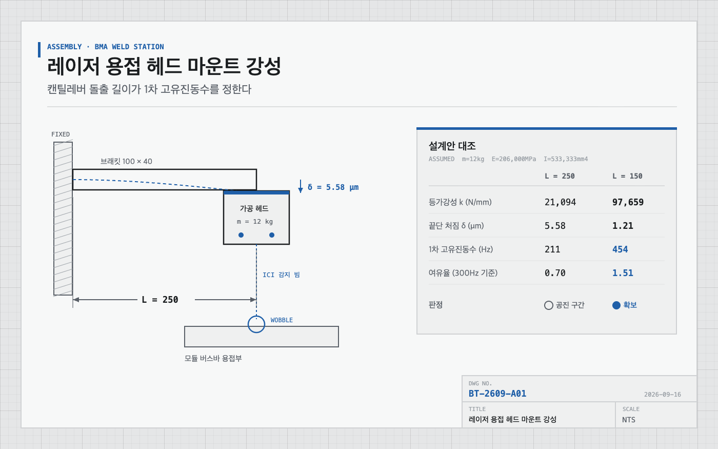
The head is modeled as a concentrated load at the end of a cantilever bracket. The end deflection, equivalent stiffness, and 1st natural frequency are as follows.
$$\delta = \frac{W L^3}{3EI},\qquad k = \frac{3EI}{L^3},\qquad f_n = \frac{1}{2\pi}\sqrt{\frac{k}{m}}$$
Here, $\delta$ is the end deflection (mm), $W$ is the head self-weight (N), $L$ is the bracket overhang length (mm), $E$ is the modulus of elasticity (MPa), $I$ is the second moment of area (mm⁴), $k$ is the equivalent stiffness (N/mm), $m$ is the head mass (kg), and $f_n$ is the 1st natural frequency (Hz).
The applied assumed values are as follows: head mass 12kg (assumed), bracket cross-section width 100mm × height 40mm, carbon steel E = 206,000MPa, second moment of area I = 533,333mm⁴, wobble frequency upper limit 300Hz (assumed). The head’s actual mass and the wobble-frequency operating range are items requiring on-site measurement and reconfirmation.
| Item | L = 250mm | L = 150mm |
|---|---|---|
| Equivalent stiffness k | 21,094 N/mm | 97,659 N/mm |
| End deflection δ | 5.58 μm | 1.21 μm |
| 1st natural frequency f_n | 211 Hz | 454 Hz |
| Vibration margin ratio (based on 300Hz) | 0.70 | 1.51 |
| Verdict | Resonance zone | Secured |
Reducing the overhang length from 250mm to 150mm changes the deflection from 5.58μm to 1.21μm, and the 1st natural frequency from 211Hz to 454Hz. The deflection improves by 4.6x, but the natural frequency improves by only 2.15x. Since static deflection is absorbed by zero-point calibration regardless, the real effect of this design change is not deflection reduction but escaping the wobble frequency band.
Dual Safety-Factor Verification
1st — Strength verification. The bending moment is $M = WL$, and the bending stress is as follows.
$$\sigma = \frac{M c}{I} = \frac{117.72 \times 250 \times 20}{533{,}333} = 1.10\ \text{MPa}$$
Assuming a carbon steel yield strength of 343MPa, the strength safety factor is approximately 311.
2nd — Vibration verification. The natural-frequency margin ratio is taken as the 1st natural frequency divided by the wobble frequency upper limit. At L = 250mm, 211/300 = 0.70, which falls within the wobble band and is a resonance zone; at L = 150mm, 454/300 = 1.51, which secures the typically recommended value of 1.5.
The two verification results are opposite. The strength safety factor of 311 is excessive, while the vibration margin ratio of 0.70 is insufficient. Reviewing strength alone, this bracket passes. This is why the safety factor must be verified in duplicate, and it is the basis for the governing condition on a measurement-equipment mount being stiffness rather than strength.
Shop-notes
- Shortening the overhang length is more effective than enlarging the cross-section. Equivalent stiffness is inversely proportional to $L^3$ and proportional to the cross-section height cubed ($h^3$), but enlarging the cross-section also increases the bracket’s own mass, offsetting the natural-frequency gain. (Machinability: a 100×40 rectangular-bar cantilever can be machined in a single milling setup. The head mounting face must be held to a flatness of 0.02/100 or better to prevent local deformation and stiffness loss after bolt tightening.)
- For the mounting bolts, span layout matters more than bolt count. The head flange bolt pitch should be widened to secure rotational stiffness; if the span is narrow, stiffness collapses at the joint even if the bracket body is enlarged.
- Alternative mechanism — direct mounting of the head to the gantry cross-beam, eliminating the bracket, was reviewed. It was not adopted because it removes the Z-axis/tilt adjustment freedom, requiring rework on model changeover when module stack heights vary by model, as on a BMA line.
- During inspection, analyze the scatter of ICI depth data by FFT to check whether a wobble-frequency component is present. If that component is detected, it is a mount problem, not a weld problem.
Design Reflection Checklist
- Secure measured head mass and center-of-gravity offset — on-site measurement and reconfirmation required
- After securing the wobble-frequency operating range, re-verify the natural-frequency margin ratio ≥1.5
- Reflect minimized bracket overhang length in the design
- Specify head mounting-face flatness of 0.02/100 on the drawing
- At initial mass production, check for resonance components via FFT of the depth signal
One-line summary: In inline depth measurement, a strength safety factor of 311 passes, yet a natural-frequency margin ratio of 0.70 fails; the governing condition of the measurement reference plane is stiffness, not strength.