In formation and charge-discharge processes, what determines the cell-to-cell pressure deviation of a pressurizing jig is not the actuator capacity but the bending stiffness of the pressure plate. Wonik PNE opened a Validation Center, an external battery evaluation facility, at its Cheongju Plant 1 and entered the testing service business by operating cyclers directly (THE ELEC, 2026-09-18). Unlike selling equipment, a testing service sells reproducibility of measured values. Reproducibility begins with whether the pressure applied to each cell is identical from cell to cell and across the entire pressurized face.
1. Problem Definition — The Resultant Force Matches, the Pressure Does Not
A pressurizing jig is normally sized by multiplying the target surface pressure by the pressurized area to determine cylinder capacity. That calculation matches only the resultant force. Even when the resultant force is correct, a deflecting pressure plate concentrates load at the center and lifts off at the edges. So how little deflection is little enough to call the pressure uniform?
The criterion is a ratio, not an absolute value. The pressure plate deflection must be sufficiently small relative to the compressive deformation of the cell stack. This review adopts the following uniformity criterion (assumed in-house criterion, to be reconfirmed by on-site measurement).
$$\delta_p \le 0.1\,\delta_c$$
Here $\delta_p$ is the maximum pressure plate deflection (mm) and $\delta_c$ is the cell stack compression (mm).
2. Kinematic Analysis — Load Path
The load travels in series from the cylinder through the pressure plate, the cell stack, the base plate and into the frame. In a series path, the most compliant element monopolizes the deformation. The cell stack is deliberately compliant, so the pressure plate upstream of it must be at least an order of magnitude stiffer than the cell. When that condition breaks, the pressure plate takes a share of the deformation, and that deformation becomes the gradient of the surface pressure distribution.
The values used in this review are listed below. The actual jig specification of the Wonik PNE center has not been disclosed, so all values are assumptions for design review purposes.
| Item | Symbol | Value | Basis |
|---|---|---|---|
| Effective pressurized area | b × L | 100 mm × 300 mm | Assumed (large-area pouch cell) |
| Target surface pressure | p | 0.30 MPa | Assumed |
| Pressurizing force per cell | F | 9.00 kN | Calculated as p × A |
| Pressure plate material | — | STS304 | Assumed, E = 193,000 MPa |
| Pressure plate thickness | h | 20 mm | Assumed |
| Support span | L | 300 mm | Simply supported at both ends, assumed |
| Cell stack compression | $\delta_c$ | 0.10 mm | Assumed, to be reconfirmed on site |
3. Calculation Verification
Converted into a uniformly distributed load:
$$w=\frac{F}{L}=\frac{9{,}000\ \mathrm{N}}{300\ \mathrm{mm}}=30\ \mathrm{N/mm}$$
The second moment of area and maximum deflection follow:
$$I=\frac{bh^{3}}{12}=\frac{100\times 20^{3}}{12}=66{,}667\ \mathrm{mm^{4}}$$
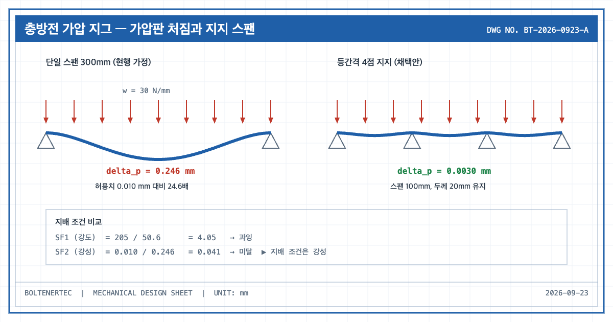
$$\delta_p=\frac{5wL^{4}}{384EI}=\frac{5\times 30\times 300^{4}}{384\times 193{,}000\times 66{,}667}=0.246\ \mathrm{mm}$$
The allowable deflection is $0.1\times 0.10=0.010$ mm, so the calculated value is 24.6 times the allowance. The practical meaning is clear. The resultant force is exactly 9.00 kN, but the surface pressure at the center and at the edges are entirely different values, and a substantial part of the cell-to-cell scatter in test data is created by the jig rather than by the cell.
The safety factor is verified twice, on strength and on stiffness. Strength first.
$$M=\frac{wL^{2}}{8}=\frac{30\times 300^{2}}{8}=337{,}500\ \mathrm{N\cdot mm}$$
$$Z=\frac{bh^{2}}{6}=\frac{100\times 20^{2}}{6}=6{,}667\ \mathrm{mm^{3}}$$
$$\sigma=\frac{M}{Z}=50.6\ \mathrm{MPa},\qquad SF_{1}=\frac{205}{50.6}=4.05$$
The yield strength of STS304 is assumed to be 205 MPa. Next is the stiffness margin, that is, the uniformity criterion.
$$SF_{2}=\frac{\delta_{allow}}{\delta_p}=\frac{0.010}{0.246}=0.041$$
The strength margin is fourfold while the uniformity margin is 0.04. The governing condition is stiffness, not strength. Meeting the stiffness requirement by thickness alone would require:
$$h \ge 20\times\sqrt[3]{24.6}=58.2\ \mathrm{mm}$$
4. Shop-notes
- Adopted solution — reduce the span, not the thickness. Dividing the span into 100 mm segments with equally spaced four-point support reduces deflection by the fourth power of span, that is to $(1/3)^{4}$ or 1/81, giving 0.0030 mm. The 20 mm thickness is retained and the 0.010 mm allowance is satisfied. The simply supported assumption ignores continuous-beam effects, so the figure is conservative.
- Machinability. Machining a 58 mm thick plate to a flatness class of 0.02 mm and holding it requires at least two cycles of aging and re-machining after tempering. Any residual heat-treatment distortion destroys the very premise of a flat initial geometry. Adding support points is superior in both machining difficulty and cost.
- Contact face. Inserting a low-hardness pad between the pressure plate and the cell absorbs local deviation, but it increases $\delta_c$, which relaxes the allowable deflection while degrading the reliability of pressure measurement. Pad thickness and hardness must be determined together with the measurement specification.
- Alternative mechanism — pneumatic bladder (air cushion) pressurization. A flexible membrane equalizes pressure automatically, so the plate stiffness problem disappears at the source. Reason for non-adoption: life and formation tests are held at elevated temperature for hundreds of hours or more, making creep and leakage management of the elastic membrane burdensome, and it is difficult to measure pressure history separately for each cell. It was judged unsuitable for testing-service equipment whose product is measurement reproducibility.
- Safety. With spring pressurization, the stored energy is released at once when pressure is relieved. A mechanical stopper must constrain the upward stroke of the pressure plate (from the entrapment-prevention standpoint of the Occupational Safety and Health Act).
5. Design Implementation Checklist
- Are the target surface pressure and the allowable pressure deviation (±%) stated separately in the specification?
- Has the cell stack compression been measured to replace the assumed 0.10 mm?
- Has the pressure plate deflection been verified to be within 10% of the cell compression?
- Have the support span and the number of support points been back-calculated from stiffness rather than strength?
- Is the pressure plate flatness tolerance of the same order or smaller than the allowable deflection?
- Is a mechanical stopper reflected in the pressure-release path?
Items Requiring Confirmation
- The pressurizing jig specification of the Wonik PNE Validation Center (surface pressure, cell format, jig structure) has not been disclosed (undisclosed).
- All dimensions, materials, surface pressures and compression values in this article are assumptions for design review and are not the actual specification of any particular equipment.
One-line summary: The cylinder sets the resultant force of a pressurizing jig, but the plate stiffness sets the pressure deviation. Reduce the span rather than increase the thickness.
Source: THE ELEC, 2026-09-18, “Wonik PNE starts up Cheongju battery test center, partners with Samsung SDI.”