For the protruding shaft of a reel-core AGV, docking accuracy is decided less by static deflection than by the change in deflection as the load moves toward the shaft tip during transfer. US12209003B2 (applicant Samsung SDS Co Ltd; priority 2020-11-16; filed 2021-07-28; granted 2025-01-28) claims an automated guided vehicle with a first shaft protruding forward from the body carrying two loading units, a camera and position adjustment module that correct the shaft-tip position, and a fixing unit that keeps loads from falling. This post calculates, stage by stage, the deflection of a cantilever shaft carrying two electrode reel cores.
1. Problem definition — does the camera-corrected position hold during transfer?
Paragraph [0089] of the specification gives 1 mm as the reference unit of position correction and an example of moving the shaft tip 5 mm left and 4 mm down. Correction is complete before transfer begins. But according to [0143], pusher 150 pushes the first object so that the second object moves onto the facility shaft. Meanwhile the load moves toward the shaft tip. So does the change in deflection after correction stay within the 1 mm reference unit?
2. Kinematic analysis — claim elements
| Element | Claim 1 feature | Mechanical interpretation |
|---|---|---|
| E1 | First shaft protruding forward from the body, first and second loading units at different positions | Cantilever with two point loads |
| E2 | Camera at one end of the shaft | Tip position measurement |
| E3 | Position adjustment module that decodes an identifier and adjusts the shaft end | Static error correction |
| E4 | First and second fixing units engaging fixing grooves in the objects | Carries inertial force while driving |
The position adjustment module absorbs static deflection at the moment of correction. It cannot absorb the change in deflection as the load position shifts afterward. That change is the design target.
3. Calculation — tip deflection by transfer stage
Design assumptions (to be reconfirmed by field measurement): object mass 150 kg × 2 (load $P$ = 1,471.5 N each), shaft overhang $L$ = 600 mm, load positions 150 mm and 450 mm, shaft S45C solid Ø80 (elastic modulus 205,000 MPa, yield 345 MPa, JIS G4051 nominal before heat treatment).
$$I=\frac{\pi d^{4}}{64}=2.01\times 10^{6}\ \mathrm{mm^{4}},\qquad \delta(a)=\frac{P a^{2}(3L-a)}{6EI}$$
Here $a$ is the distance from the fixed end to the load (mm) and $\delta(a)$ is the tip deflection from that load (mm).
| Stage | Load positions | Tip deflection |
|---|---|---|
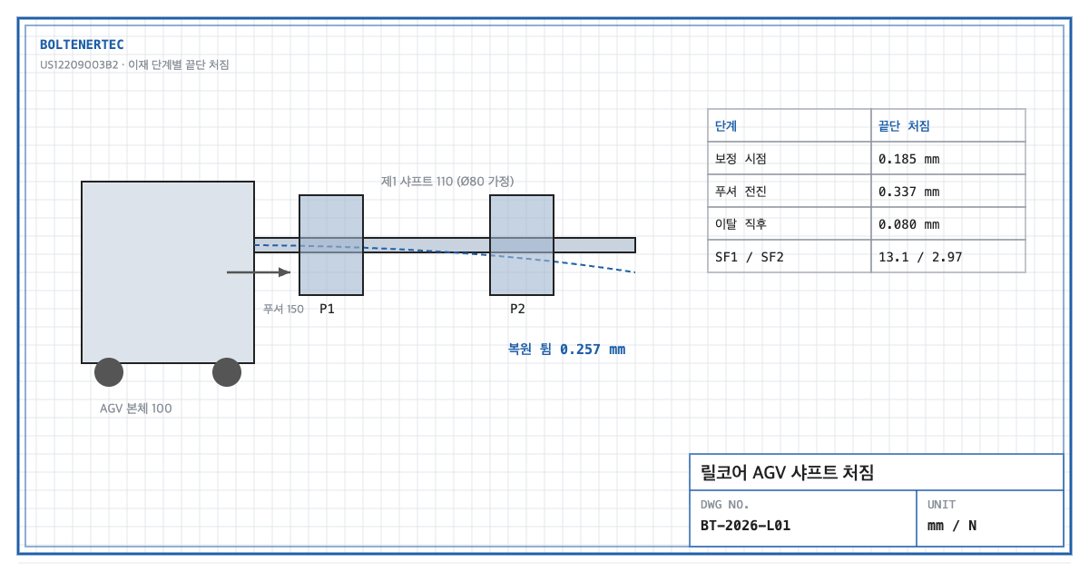
| At correction (loaded) | 150 mm, 450 mm | 0.185 mm |
| Pusher advanced (second object at tip) | 300 mm, 600 mm | 0.337 mm |
| Just after second object leaves | 300 mm | 0.080 mm |
After correction the tip drops another 0.152 mm, then springs up 0.257 mm the moment the object leaves. This rebound is what causes interference with the facility shaft.
$$\sigma=\frac{P(300+600)}{\pi d^{3}/32}=26.3\ \mathrm{MPa},\qquad SF_{1}=\frac{345}{26.3}=13.1$$
$$SF_{2}=\frac{1.0}{\delta_{max}}=\frac{1.0}{0.337}=2.97$$
The strength margin is 13.1 and the deflection margin against the 1 mm correction unit is 2.97. Enlarging the shaft to Ø100 reduces maximum deflection to 0.138 mm but adds 56% mass, eating into AGV payload.
The fixing-unit load while driving is also checked. At a braking deceleration of 0.5 m/s² (assumed), the inertial force per object is $m a$ = 75 N. The fixing-groove engagement must carry this horizontal force plus the rise in deceleration at emergency stop.
4. Shop-notes
- A chamfer of 0.5 mm or more at the facility shaft entry. Given the 0.257 mm rebound and the 1 mm correction unit, absorbing it with an entry chamfer is more economical than enlarging the shaft.
- Machinability. Turn the shaft integral with its fixed-end flange, then heat-treat. Specify 0.05 mm tip runout after heat treatment and finish-grind the OD after heat treatment if needed.
- Alternative mechanism — tip support roller. A support roller on the facility side turns the cantilever into a simply supported beam and greatly reduces deflection. Not adopted because: every facility needs a support structure, and AGV stop-position error turns into roller contact impact.
- Safety. The pusher stroke zone is a pinch zone between object and facility shaft. Define a protected area that keeps workers out during transfer.
5. Design checklist
- Was tip deflection calculated for every transfer stage (correction, pusher advanced, just after release)?
- Is the post-correction deflection change within the facility entry chamfer?
- Were shaft strength $SF_1$ and deflection $SF_2$ checked separately?
- Does the fixing unit carry inertial force at emergency-stop deceleration?
- Is pinch protection in the pusher zone included?
Items requiring confirmation
- Shaft length, reel-core mass and material are not stated in the specification. The only specification figures are the position-correction example (1 mm unit, 5 mm and 4 mm moves); calculated values here are assumptions.
- The wording of claim 1 should be reconfirmed against the original publication.
One-line summary: The reel-core AGV shaft has a 13.1 strength margin, but a 0.257 mm rebound during transfer causes docking interference, so it must be absorbed by an entry chamfer on the facility side.
Source: US12209003B2, “Automated guided vehicle and method for transporting electrode reel core using thereof”, claim 1 and specification [0089], [0131], [0143].