A two-row gripper on a formation jig is not a structure that simply adds gripping points; it is a structure in which the parallelism between the two rows decides how the gripping force is shared. KR101076412B1 “Battery formation jig” (applicant ETH Co., Ltd.; filed 2009-07-07; granted 2011-10-25; now lapsed for non-payment of fees) claims support plates and gripper assemblies on both faces of an electrode tab, with the gripper assemblies arranged in upper and lower rows. This post reviews, in numbers, the geometric condition for both rows to press the tab with the same force.
1. Problem definition — are two rows twice as stable?
Each gripper assembly carries elastic contact pieces 37 for current and 47 for voltage. An elastic contact piece is a spring. When two rows of springs sit on one gripper block, a tilted block presses one row harder and the other row less. So does the contact reliability of a two-row structure depend on block tilt rather than on spring performance?
2. Kinematic analysis — claim element breakdown
| Element | Claim 1 feature | Mechanical interpretation |
|---|---|---|
| E1 | First support plates 150 and gripper assemblies 70 approach both faces of one tab | Two-sided clamp |
| E2 | Gripper assembly rows arranged as upper and lower rows | Rigid block on two supports |
| E3 | Second part 200 with the same structure on the other tab | Left–right symmetric part |
| Drive | Cylinder 172, stopper block 174, hinge portion 174a (specification) | Hinged rotary approach |
A block that closes by rotating about a hinge is not guaranteed to be parallel to the support plate in the closed position. Errors in hinge-axis position and stopper height become block tilt $\theta$ directly.
3. Calculation — tilt and gripping-force imbalance
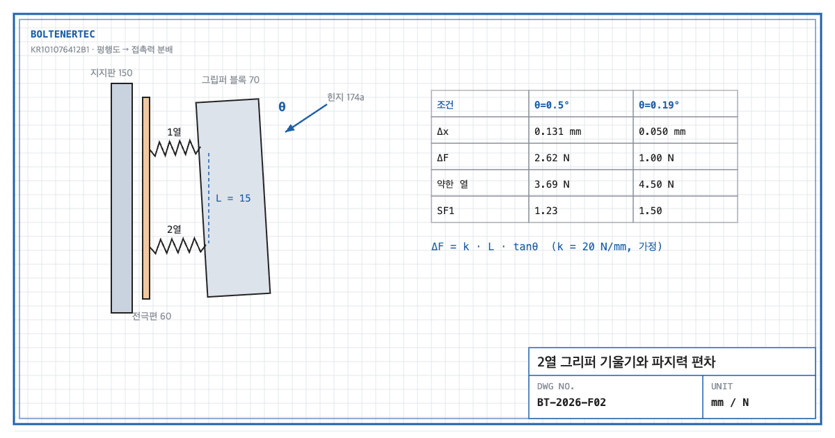
Design assumptions (to be reconfirmed by field measurement): contact-piece spring rate $k$ = 20 N/mm, row spacing $L$ = 15 mm, nominal contact force $F_0$ = 5 N per row, minimum required force $F_{req}$ = 3 N per row, block tilt $\theta$ = 0.5°.
$$\Delta x = L\tan\theta = 15\times\tan 0.5^{\circ}=0.131\ \mathrm{mm}$$
$$\Delta F = k\,\Delta x = 20\times 0.131 = 2.62\ \mathrm{N}$$
Here $\Delta x$ is the difference in compression between the rows (mm) and $\Delta F$ is the contact-force difference (N). The imbalance splits as ±1.31 N, or ±26% of the 5 N nominal.
$$SF_{1}=\frac{F_0-\Delta F/2}{F_{req}}=\frac{5-1.31}{3}=1.23$$
The weak row has a contact-force margin of only 1.23. This margin is easily consumed if tab heating during formation shifts contact resistance.
The second check is the deformation margin of the contact piece itself. The nominal compression $\delta_0=F_0/k$ = 0.25 mm plus 0.065 mm extra on the harder-pressed row. With an elastic-limit displacement of 0.8 mm (assumed; replace with material certificate value):
$$SF_{2}=\frac{\delta_{el}}{\delta_0+\Delta x/2}=\frac{0.8}{0.25+0.065}=2.54$$
The deformation margin is sufficient. The governing condition is not the spring but the minimum force of the weak row, i.e., block tilt.
To hold the imbalance to ±10% (±0.5 N), $\Delta x \le 0.05$ mm is required. At 15 mm row spacing that is a tilt of 0.19° or less, which equals a parallelism of 0.05 mm between the gripper face and the support plate. $SF_1$ then rises to (5 − 0.5)/3 = 1.5.
4. Shop-notes
- Specify parallelism in the closed position after assembly. Control 0.05 mm parallelism between gripper face and support plate as an assembly tolerance with the hinge closed, not as single-part parallelism. Provide a shim seat on stopper block 174 for correction at assembly.
- Machinability. Machine the stopper contact face and the hinge-axis bore in one clamping to reduce position error. Separate setups accumulate tilt error.
- Alternative mechanism — self-aligning pin in the block. Supporting the gripper block on a central pin lets it rock and balance both rows automatically. Not adopted because: the rocking freedom degrades position repeatability of the current and voltage contacts, and pin wear becomes a new source of play.
- Safety. The cylinder-driven hinge closing zone is a finger pinch hazard. Apply a guard or two-hand operation between the cell loading position and the hinge rotation path.
5. Design checklist
- Was the row force difference calculated as $k L \tan\theta$?
- Is $SF_1$ ≥ 1.5 secured on the weak row’s minimum contact force?
- Is the closed-position assembly parallelism (0.05 mm) specified on the drawing?
- Is a stopper shim seat included in the design?
- Is hinge rotary-zone guarding included?
Items requiring confirmation
- Spring rate, contact force and row spacing are not stated numerically in the specification. All figures here are review assumptions.
- The minimum required contact force depends on current conditions and contact material; reconfirm by field measurement.
One-line summary: At 0.5° tilt the weak row of a two-row gripper drops to a 1.23 contact margin, so the controlled item is the 0.05 mm closed-position parallelism, not the spring.
Source: KR101076412B1, “Battery formation jig”, claim 1 and reference-numeral description (gripper assembly 70, elastic contact pieces 37·47, cylinder 172, hinge portion 174a).