In the C-shaped terminal connector of a charge/discharge jig, contact quality is decided not by body stiffness but by the slip margin of the slit clamp and the stroke setting of the pressing part. KR101029019B1 (applicant LG Chem, now LG Energy Solution; filed and prioritized 2007-01-19; granted 2011-04-14) claims first and second members coupled variably along the cell length, and a terminal connection part with a body that is ‘ㄷ’-shaped (C-shaped) in vertical cross-section plus a pressing part. This post calculates how far the C-shaped body opens under the pressing reaction and whether that value actually matters.
1. Problem definition — does an opening C-frame lose contact force?
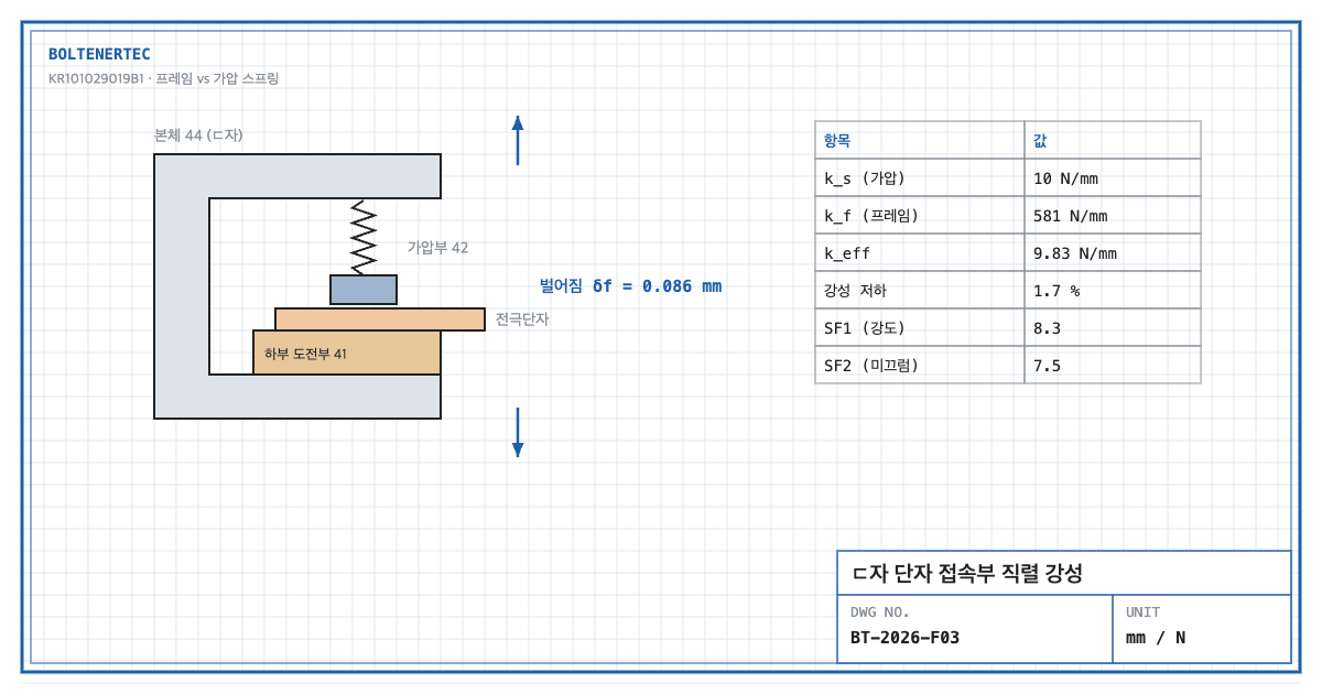
The C-shaped body holds the electrode terminal; a conductive portion contacts the terminal’s lower face and the pressing part presses its upper face. The reaction of the pressing force spreads the upper and lower arms of the body, like a C-clamp. If the body opens, pressing stroke is consumed and contact force drops. So how thick must the body be?
The other variable is the variable coupling. The specification sets the overlap between the first and second members at 40–90% of member length and shows about 45% in the drawing example. The overlap is fixed with slit 22 and male threaded fastener 24.
2. Kinematic analysis — a series spring model
| Component (reference numeral) | Mechanical role | Model |
|---|---|---|
| Body 44 (C-section) | Holds terminal, carries reaction | C-frame stiffness $k_f$ |
| Pressing part 42 | Presses terminal upper face | Pressing spring $k_s$ |
| Lower conductive portion 41 | Contacts terminal lower face | Contact face |
| Slit 22, fastener 24 | Fixes variable member length | Friction joint |
The pressing spring and the C-frame are in series. Effective stiffness is $k_{eff}=1/(1/k_s+1/k_f)$. If $k_f$ is much larger than $k_s$, frame deformation is negligible.
3. Calculation — frame stiffness and joint slip
Design assumptions (to be reconfirmed by field measurement): pressing force $F$ = 50 N, arm length $e$ = 10 mm, back height $h$ = 20 mm, section width $b$ = 10 mm, thickness $t$ = 3 mm, Al 6061-T6 (elastic modulus 68,900 MPa, yield 276 MPa, ASM Handbook nominal), pressing spring $k_s$ = 10 N/mm.
$$I=\frac{b t^{3}}{12}=\frac{10\times 3^{3}}{12}=22.5\ \mathrm{mm^{4}}$$
$$\delta_f=\frac{2F e^{3}}{3EI}+\frac{F e^{2} h}{EI}=0.086\ \mathrm{mm}$$
Here $\delta_f$ is the opening of the C-frame mouth (mm). The first term is bending of both arms; the second is arm rotation from bending of the back. Frame stiffness is $k_f=F/\delta_f$ = 581 N/mm.
$$k_{eff}=\frac{1}{1/10+1/581}=9.83\ \mathrm{N/mm}$$
The loss of effective stiffness is 1.7%. Even a 3 mm body loses negligible contact force. There is no reason to enlarge the body on stiffness grounds.
$$\sigma=\frac{F e}{b t^{2}/6}=\frac{500}{15}=33.3\ \mathrm{MPa},\qquad SF_{1}=\frac{276}{33.3}=8.3$$
The body strength margin is 8.3.
The second check is slip of the slit joint. Assume an M4 fastener, tightening torque $T$ = 2.0 N·m, nut factor $K$ = 0.2, friction coefficient $\mu$ = 0.15.
$$F_i=\frac{T}{K d}=\frac{2{,}000}{0.2\times 4}=2{,}500\ \mathrm{N},\qquad F_{slip}=\mu F_i=375\ \mathrm{N}$$
$$SF_{2}=\frac{F_{slip}}{F}=\frac{375}{50}=7.5$$
Slipping of the variable joint under the pressing reaction is unlikely. But half the tightening torque halves $SF_2$. The margin comes from torque control.
4. Shop-notes
- The controlled item is pressing stroke. With only 1.7% frame loss, contact force is set by the initial compression of the pressing spring. A ±0.1 mm compression error gives ±1 N (±2%). Make the pressing-part stopper height adjustable.
- Machinability. Cutting the C-body from aluminum extrusion and only finishing the mouth with an end mill keeps cost low. Specify 0.02 mm flatness on the lower conductive contact face and decide on lapping after assembly.
- Alternative mechanism — toggle-clamp terminal pressing. A toggle produces high force near dead center. Not adopted because: terminal thickness variation is amplified into force variation, degrading contact consistency. Spring pressing is better for force control.
- Torque marking. Apply torque marks to the variable-joint fasteners to prevent missed re-tightening after a cell-length change.
5. Design checklist
- Were the pressing spring and frame calculated as series stiffness?
- Was $k_f/k_s$ ≥ 10 confirmed?
- Was the slit-joint slip factor calculated at the lower limit of tightening torque?
- Was the clamping length checked at the minimum 40% overlap?
- Are the adjustable stopper and contact-face flatness specified?
Items requiring confirmation
- The only numeric values in the specification are the overlap range (40–90%, about 45% in the drawing). Force, dimensions and material are not stated; figures here are assumptions.
- The wording of claim 1 should be reconfirmed against the original publication.
One-line summary: The C-body opening costs only 1.7% of contact force, so contact quality must be managed through pressing stroke and tightening torque, not body thickness.
Source: KR101029019B1, “Jig for charge/discharge of secondary batteries”, claim 1, dependent claim (overlap range) and drawing description.