The design limit of a rail-mounted roll loading/unloading unit beside an unwinder is not rail strength but overturning stability while the rotating body holds the roll at an eccentric position. EP4159653B1 (proprietor SK On Co., Ltd.; priority KR 2021-09-29; filed 2022-09-28; grant mentioned 2024-07-24; US family US11958705B2 granted 2024-04-16) claims a roll support portion adjacent to a roll unwinder, a first traveling rail on one side of the unwinder, a moving frame on the rail, and a roll attaching/detaching unit on the moving frame. The unit consists of a moving plate and a main body portion rotatably mounted on it. This post calculates the wheel reactions of the moving frame from roll eccentricity and wheelbase.
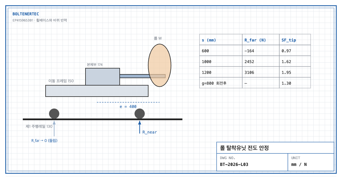
1. Problem definition — when the roll is extended, does the far wheel lift?
Detachable fork 177 extends away from the moving-frame center to fit the roll on, or remove it from, the unwinder shaft. The farther the roll’s center of gravity moves from the frame center, the larger the near-wheel reaction and the smaller the far-wheel reaction. When the far reaction reaches zero, the frame lifts. When the main body rotates, the direction of eccentricity also changes. So how large must the wheelbase and the rail gauge each be?
2. Kinematic analysis — claim elements
| Element | Claim 1 feature | Mechanical interpretation |
|---|---|---|
| E1 | Roll support portion 120 adjacent to the unwinder, including lifting unit 126 | Handoff height adjustment |
| E2 | First traveling rail 130 on one side of the unwinder | Load-transfer foundation |
| E3 | Moving frame 150 movable on the rail | Wheel reaction distributor |
| E4 | Moving plate 172 + rotatable main body portion 174 | Source of eccentric load |
The specification states no dimensions, roll weight or speeds (checked in the full EPO publication). The calculation below is therefore an assumed case that illustrates the design review procedure.
3. Calculation — wheel reactions and overturning factor
Design assumptions (to be reconfirmed by field measurement): roll mass 1,000 kg ($W$ = 9,810 N), self-weight of moving frame and detaching unit 300 kg ($W_f$ = 2,943 N, acting at frame center), roll eccentricity $e$ = 400 mm, wheelbase $s$.
$$R_{near}=\frac{W+W_f}{2}+\frac{W e}{s},\qquad R_{far}=\frac{W+W_f}{2}-\frac{W e}{s}$$
$$SF_{tip}=\frac{(W+W_f)\,s/2}{W e}$$
Here $R$ is the reaction of a wheel line (N) and $SF_{tip}$ is the overturning safety factor.
| Wheelbase $s$ | $R_{near}$ | $R_{far}$ | $SF_{tip}$ |
|---|---|---|---|
| 600 mm | 12,916 N | −164 N | 0.97 |
| 1,000 mm | 10,300 N | 2,452 N | 1.62 |
| 1,200 mm | 9,646 N | 3,106 N | 1.95 |
At a 600 mm wheelbase the far reaction is negative, meaning the frame lifts. Widening the wheelbase to 1,000 mm gives $SF_1$ = $SF_{tip}$ = 1.62.
The second check is the allowable wheel load. At a 1,000 mm wheelbase, two near-side wheels share 10,300 N, or 5,150 N each. Against an allowable wheel load of 10 kN (assumed; replace with the manufacturer’s catalog value):
$$SF_{2}=\frac{10{,}000}{5{,}150}=1.94$$
When the main body rotates 90°, the eccentricity turns toward the rail-gauge direction. With a rail gauge $g$ = 800 mm (assumed), the overturning factor in that direction is $(W+W_f)g/2 \div We$ = 1.30. It reaches its limit before the wheelbase direction. Stability in the post-rotation eccentric direction is the actual governing condition.
Rotation drive torque is also checked. Approximating the roll as a point mass at 0.4 m radius gives $J$ = 160 kg·m². Rotating 90° in 3 s with a trapezoidal profile (1 s each for acceleration and deceleration) needs 0.785 rad/s² angular acceleration and a torque of $J\alpha$ = 126 N·m. The reducer is selected by adding friction and starting margin to this value.
4. Shop-notes
- Reduce eccentricity; if you cannot, add an upper guide. An arrangement that reduces roll eccentricity at fork extension comes first. If eccentricity is unavoidable, fit anti-lift guide rollers (up-stops) on the moving frame that hook under the rail flange to constrain lifting mechanically.
- Machinability. The moving frame is a weldment. After stress-relief annealing, line-bore the wheel-axle holes in one setup. Specify 0.1 mm wheel-axle parallelism to prevent uneven rail wear.
- Alternative mechanism — counterweight. A weight opposite the eccentricity raises the overturning factor. Not adopted because: wheel and rail loads rise together, and larger rotational inertia increases drive torque. Securing wheelbase and rail gauge comes first.
- Safety. The traveling-rail zone is a crush hazard. Install mechanical stoppers and buffers at both rail ends and fence the travel zone.
5. Design checklist
- Is roll eccentricity at maximum fork extension fixed?
- Is an overturning factor ≥ 1.5 secured in both wheelbase and rail-gauge directions?
- Was the far-wheel reaction confirmed to be positive?
- Was the per-wheel load checked against the catalog allowable?
- Was main-body rotation torque calculated from inertia and acceleration time?
Items requiring confirmation
- Roll mass, eccentricity, wheelbase and rail gauge are not stated in the specification. All figures here are assumptions.
- Allowable wheel load should be reconfirmed from the catalog of the product applied.
One-line summary: At a 600 mm wheelbase the far wheel of the roll unloading unit lifts, so the overturning factor must first be secured in both the wheelbase and post-rotation rail-gauge directions.
Source: EP4159653B1, “Apparatus for loading and unloading roll”, claim 1 and reference-numeral description; family US11958705B2.