Problem Definition
Dry electrode calendering is a process that rolls powder into a film between rolls at the nip, without solvent.
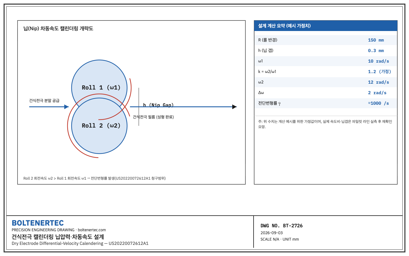
Unlike the wet slurry process, there is no drying oven, reducing equipment footprint and energy consumption.
In a patent filed in January 2020 and published in March 2022 (Publication No. US20220072612A1, Application No. US17/422,966, originally filed by Maxwell Technologies, now assigned to Tesla Inc.), Tesla claimed a structure that controls the rotational speed of the 2nd calendering roll to be higher than that of the 1st roll.
The starting point of this patent is that if the two rolls’ speeds are equal, the shear force needed for bonding between powder particles is insufficient, resulting in non-uniform film density and strength.
When a domestic electrode-process equipment maker converts a wet line to dry, the practical question that remains is what roll speed ratio must be designed to achieve the target density without film rupture.
Kinematic Analysis
When the two rolls forming the nip rotate at different circumferential speeds, a shear strain rate is generated at the contact surface.
The shear strain rate can be approximated as the speed difference between the two rolls divided by the nip gap.
The larger the speed difference, the more frictional heat generation between powder particles and fibrillation of the binder (such as PTFE) is promoted, but an excessive speed difference causes film surface scratching and thickness deviation.
The patent specification does not numerically limit a specific speed ratio, leaving only the relative claim that “Roll 2 is faster than Roll 1.”
The actual speed ratio is an area each company must determine experimentally depending on binder composition and roll surface friction coefficient (undisclosed).
Calculation and Formula Verification
The shear strain rate approximation formula is as follows.
$$\dot{\gamma} \approx \dfrac{(\omega_2 – \omega_1) R}{h}$$
Here, $\dot{\gamma}$ is the shear strain rate (1/s), $\omega_1, \omega_2$ are the angular velocities of Roll 1 and Roll 2 (rad/s), $R$ is the roll radius (mm), and $h$ is the nip gap (mm).
Assumed values for verification (field measurement re-confirmation required; the figures below are estimates for a calculation example): $R = 150$ mm, $h = 0.3$ mm, $\omega_1 = 10$ rad/s, speed ratio $k = \omega_2/\omega_1 = 1.2$.
In this case, $\omega_2 = 12$ rad/s, $\Delta\omega = 2$ rad/s, and $\dot{\gamma} \approx (2 \times 150)/0.3 = 1000$ /s results.
A shear strain rate in the 1000/s range falls within the hundreds-to-thousands /s range reported for the onset of PTFE fibrillation, so a qualitative judgment is possible that the above combination is a candidate design point for inducing fibrillation.
However, the critical shear strain rate varies with binder lot and particle size distribution, so it is not a fixed value, and pilot-line measurement is required.
From the nip pressure perspective, roll deflection is another cause of film thickness deviation. The simple-supported-beam approximation formula is as follows.
$$\delta = \dfrac{F L^3}{48 E I}$$
$\delta$ is the roll center deflection (mm), $F$ is the nip reaction force (N), $L$ is the roll effective length (mm), $E$ is the elastic modulus (MPa), and $I$ is the second moment of area (mm⁴).
The safety factor must be double-verified: first, allowable stress against roll shaft bending stress; second, actual reaction force against bearing dynamic rated load.
If either criterion is not met, the design must be reviewed.
Practical Application — Shop-notes
As an alternative mechanism, variable speed-ratio control using individual servo-motor drives plus encoder feedback was reviewed.
This method can correct the speed ratio in real time according to line speed changes, but the phase-difference risk of two-channel servo synchronous control and the increase in equipment cost are the reasons it was not adopted.
On the pilot line, it is reasonable to first verify the speed ratio with a fixed gear train, and reconsider servo conversion when transitioning to the mass-production line.
Machinability note: the calendering roll surface must achieve a surface roughness of Ra 0.2 or less through chrome plating followed by grinding, and chamfering at the boundary between the roll base material and the plating layer must be performed beforehand to prevent plating delamination.
The differential-speed drive shaft requires spline machining tolerance control per KS B ISO 4156.
The nip opening must apply an entrapment-prevention guard (opening 6 mm or less, or interlock) in accordance with the entrapment-prevention standards of the Occupational Safety and Health Act.
Design Reflection Checklist
- Confirm roll speed ratio k value through pilot-line measurement
- Set nip gap h control range and link to interlock
- Prepare dual safety-factor calculation report for roll shaft bending stress and bearing rated load
- Design entrapment-prevention guard (reflecting Occupational Safety and Health Act standards)
- Reflect chrome-plated roll surface roughness Ra 0.2 or less in machining specification
One-Line Summary
The core of dry electrode calendering is not the nip pressure value itself but the shear strain rate created by the speed difference between the two rolls, and the speed ratio is an undisclosed variable that must be determined through material-lot-specific measurement.