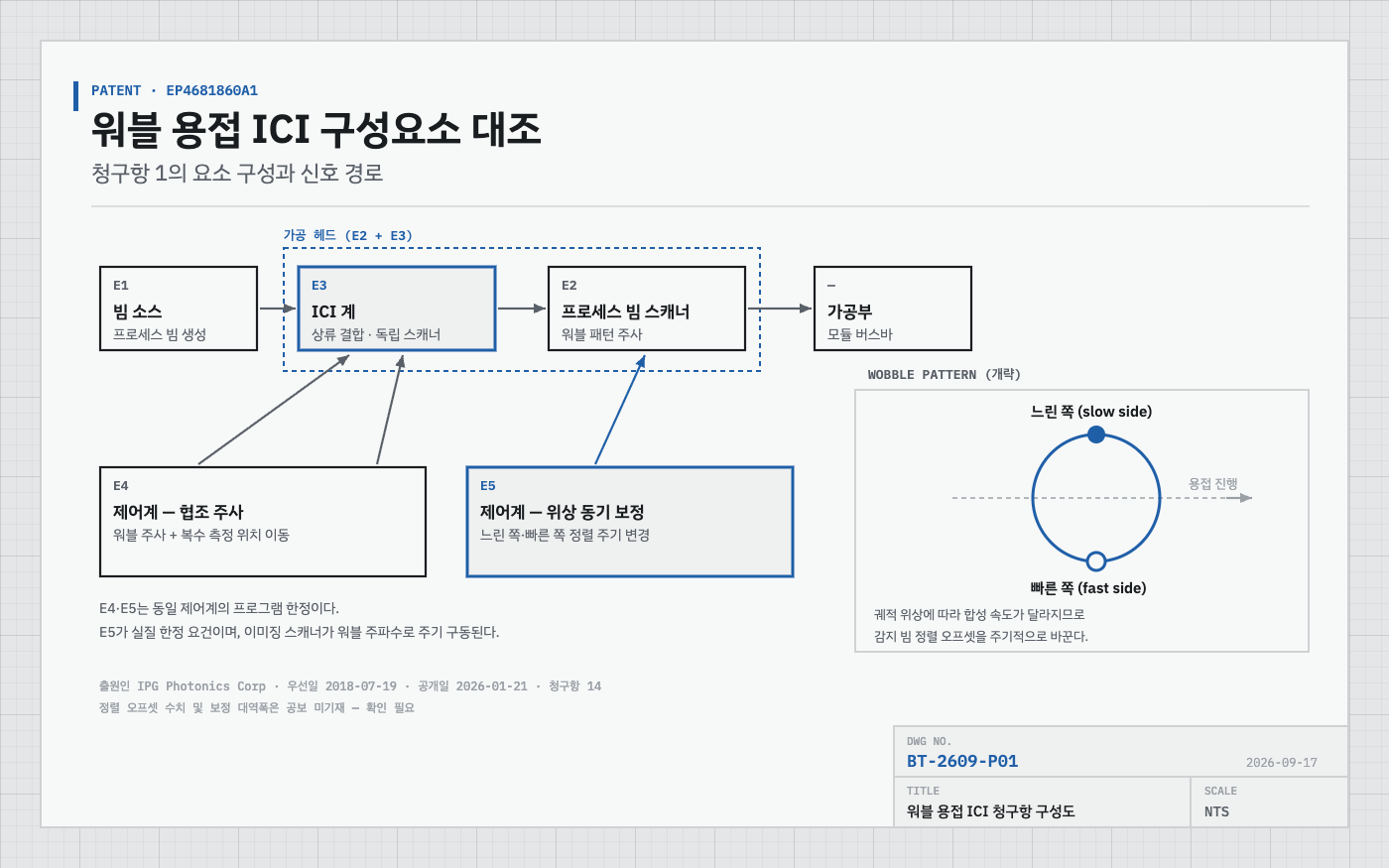
The substantive limitation of EP4681860A1 is not the placement of the ICI system, but the periodic alignment correction for the slow side and fast side of the wobble trajectory.
Bibliographic Information
| Publication number | EP4681860A1 |
| Title | System and method for monitoring and/or controlling wobble-processing using inline coherent imaging (ICI) |
| Applicant | IPG Photonics Corp |
| Priority date | 2018-07-19 |
| Original filing date | 2019-07-18 |
| European application number | EP25192841.2A |
| Publication date | 2026-01-21 |
| Number of claims | 14 |
Prompted by a report that LG Energy Solution applied IPG Photonics laser-weld non-destructive inspection equipment to a US ESS module assembly line (The Elec, 2026-09-15), the same applicant’s wobble-welding ICI publication was reviewed element by element.
Claim 1 Element Comparison Table
| Element | Claim 1 Substance | Target Equipment Correspondence (General Module Weld Station) | Mechanical Design Impact |
|---|---|---|---|
| E1 | A material-modification beam source generating a process beam | Welding fiber laser oscillator | Secure minimum fiber bend radius; fixed bracket at the lead-out section |
| E2 | A processing head coupled to the beam source, including a process-beam scanning actuator for one or more axes, that directs and moves the beam over the workpiece in a wobble pattern | Welding head with integrated wobble scanner | Mirror angular-acceleration reaction force is input to the head housing as a periodic load at the wobble frequency |
| E3 | An ICI system optically coupled to the processing head upstream of the process-beam scanning actuator, positioning an imaging beam at least partially independently of the process beam via its own imaging-beam scanning actuator | Coaxial depth-measurement module | Requires two scanner sets inside the head → increases head mass and inertia |
| E4 | A control system programmed to control the beam source, the process-beam scanner, and the imaging-beam scanner, scanning the process beam in a wobble pattern and moving the imaging beam to multiple measurement positions on the workpiece in coordination with the wobble pattern | Weld/measurement synchronization controller | Measurement-position coordinates are dependent on the head coordinate system → head displacement directly becomes measurement error |
| E5 | A control system programmed to correct alignment by moving the imaging beam relative to the process beam based at least in part on the beam position on the wobble pattern, periodically varying the alignment for the slow side and fast side of the wobble pattern | Correspondence undisclosed | The imaging scanner is also periodically driven at the wobble frequency → an additional excitation source |
Mechanism-Perspective Analysis
What E3 requires is not simple coaxial measurement. The ICI system is optically coupled upstream of the process-beam scanner, while also having its own scanning actuator. As a result, the head interior contains a separate galvo for the process beam and for the imaging beam, respectively. Compared to a configuration with a single scanner set, this increases head mass and inertia, which directly pulls down the 1st natural frequency of the bracket supporting the head.
The substantive limitation lies in E5. The wobble trajectory’s travel speed differs by position along the trajectory. In the section where the welding travel direction and wobble rotation direction align, the combined speed is fast; in the opposite section, it is slow. The slow side has a larger heat input per unit length and the fast side a smaller one, so the keyhole shape and depth vary with trajectory phase. Therefore, if the sensing beam is fixed at the same point as the process beam, it ends up measuring a different point at each phase. E5 handles this error through periodic alignment correction synchronized to the trajectory phase.
From a mechanical design perspective, the significance of this clause is clear. Since the imaging scanner is periodically driven at the wobble frequency, the imaging scanner’s reaction force adds to the process scanner’s reaction force at the same frequency. The mount design must not assume a single excitation source; it must presuppose the worst-case condition where the reaction forces of both scanners overlap in phase. This is the basis for why reviewing the natural-frequency margin ratio of the head mount becomes essential.
Items Requiring Confirmation
- Head mass and moment of inertia: values not stated in the publication — confirmation required
- Magnitude of the slow-side/fast-side alignment offset and correction bandwidth: values not stated in the publication — confirmation required
- Internal configuration of the actually delivered equipment: undisclosed
This analysis organizes the elements of Claim 1 within the scope disclosed in the published publication EP4681860A1. The target-equipment column is a correspondence based on a general module weld-station configuration and does not determine infringement by any specific vendor’s equipment.
One-line summary: The substantive limitation of EP4681860A1 Claim 1 is alignment correction of the sensing beam synchronized to the wobble-trajectory phase, which is a condition that adds one more excitation source at the same frequency to the head mount.