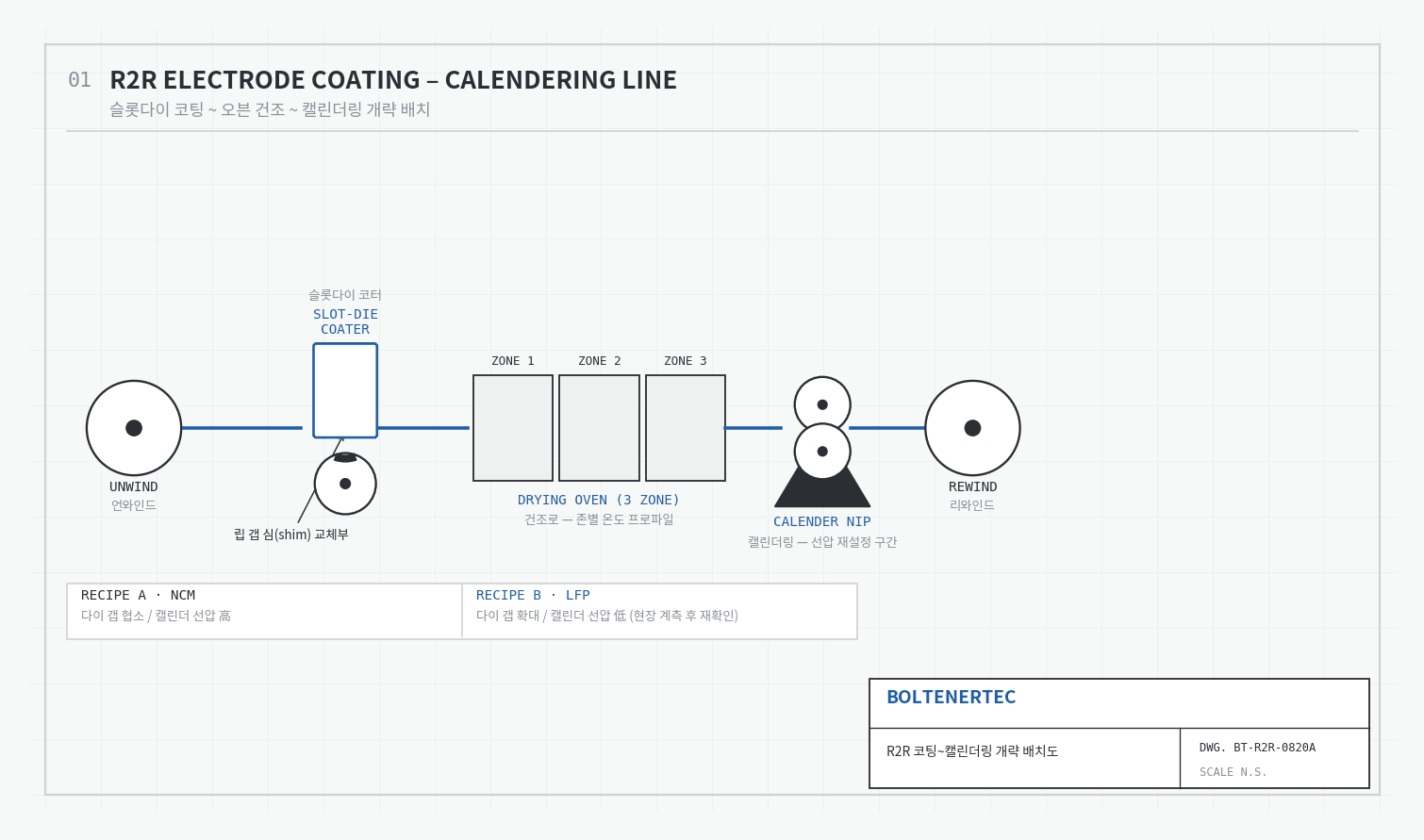
Problem Definition
LFP electrode coating is a process that applies slurry with lower solids content and viscosity than NCM using a slot-die coater. Conventional R2R lines are designed around a single chemistry, with die lip gap, oven zone temperature, and calender line load fixed as constant values. LG Energy Solution’s Lansing plant has transitioned to a system that produces ESS-bound LFP cells and Toyota-bound NCM cells in parallel at the same site (source: electrive, 2026-08-19). Alternating the two slurries through the same coater requires a mechanism that can switch die gap and calender nip pressure between chemistries quickly and reproducibly. This is where the mechanical contradiction arises: widening the die gap can compensate for LFP’s lower solids content, but every time the lip joint surface is reassembled, the risk of leakage and thickness deviation increases. Where should the gap-changing mechanism be placed to minimize the burden of assembly tolerance management?
Kinematic Analysis
Wet coating thickness is determined by flow rate and web speed.
$$t_{wet} = \frac{Q}{w \cdot v}$$
$t_{wet}$ is the wet coating thickness (mm), $Q$ is the slurry discharge flow rate (mm³/s), $w$ is the web width (mm), and $v$ is the web speed (mm/s). The die lip gap must be larger than $t_{wet}$ to stay within the coating window. Because LFP has lower solids content, achieving the same dry thickness requires increasing both $t_{wet}$ and the lip gap together (the solids-content gap varies by formulation, so on-site measurement and reconfirmation is required). Gap adjustment standardly uses lip shim replacement, and the key question is whether the lip clamp bolts withstand the slurry’s internal pressure and reproduce joint-surface flatness with every shim change.
Calculation/Formula Verification
The separating force over one pitch section of the lip clamp bolts is as follows.
$$F_{sep} = P \cdot p \cdot b$$
$P$ is the slurry internal pressure (MPa), $p$ is the bolt pitch (mm), and $b$ is the effective width of the lip opening (mm). As a design example, substituting $P=0.3\,\text{MPa}$ (estimated, on-site measurement and reconfirmation required), $p=50\,\text{mm}$, and $b=30\,\text{mm}$ gives $F_{sep}=450\,\text{N}$.
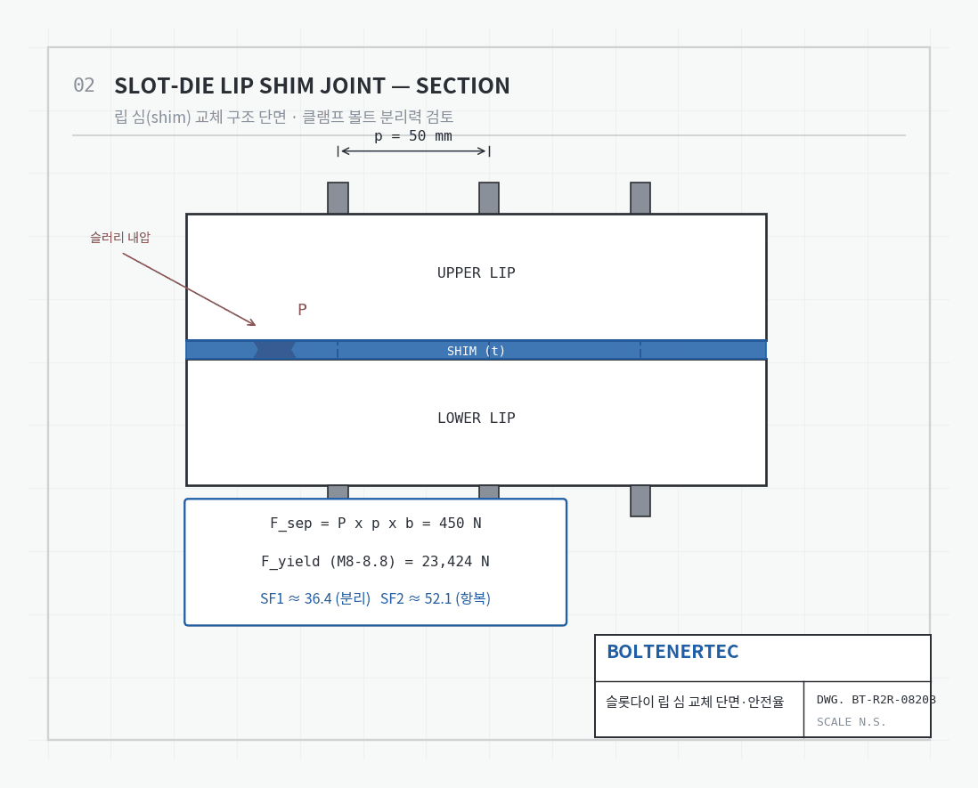
For an M8 grade 8.8 bolt with effective cross-sectional area $A_s=36.6\,\text{mm}^2$ and yield strength $\sigma_y=640\,\text{MPa}$ (per ISO 898-1), the allowable tensile force at yield is
$$F_{yield} = \sigma_y \cdot A_s = 640 \times 36.6 = 23{,}424\,\text{N}$$
Setting the clamping preload at 70% of yield ($F_{pre}\approx16{,}397\,\text{N}$) gives a first safety factor (against separation) of $SF_1=F_{pre}/F_{sep}\approx36.4$, and a second safety factor (against bolt yield) of $SF_2=F_{yield}/F_{sep}\approx52.1$. Both values carry large margin. Bolt clamping force is not the cause of leakage after shim replacement. In practice, the recurring cause of leakage is not the bolts but the lip joint-surface flatness error remaining after a shim change.
Shop-notes
| Category | Control Standard |
|---|---|
| Shim material | SUS303 or SK5, wire-cut (WEDM) machined |
| Shim thickness tolerance | ±0.01 mm (minimum condition for reproducibility) |
| Bolt re-tightening torque | Follow specified torque, three-step diagonal tightening sequence |
| Calender line load | Reset lower than NCM when applying LFP (reduction magnitude requires on-site measurement and reconfirmation) |
A lip-gap servo actuator for real-time adjustment was considered as an alternative but not adopted. The reason is that lip deflection stiffness under slurry pressure fluctuation has not been verified, and it would mean prioritizing a control solution ahead of mechanical design. The shim-replacement method, while structurally simpler, offers higher reproducibility. Machinability note: the ±0.01mm shim thickness tolerance requires lapping in addition to surface grinding; wire-cut machining alone leaves batch-to-batch variation.
One-Line Summary
What prevents leakage during the LFP transition is not bolt clamping force but flatness tolerance management of the shim joint surface.