| Item | Content |
|---|---|
| Publication number | KR 10-2019-0124040 A (published 2019-11-04) |
| Registration number | KR 10-2261165 B1 (granted 2021-06-07) |
| Title | Secondary battery static pressure jig and secondary battery internal pressure control method using the same |
| Applicant | LG Chem, Ltd. |
| Inventors | Ha Hoe-jin, Lee Jeong-beom |
| Filing / priority date | 2018-04-25 (KR 10-2018-0048098) |
| Family | WO2019208929A1, EP3675272B1, CN111183547A, US11454556B2 |
| Number of claims | 15 |
| Legal status | Active (anticipated expiration 2038-04-25) |
The conventional design of a pressurizing jig presses with a constant force. The specification points out that this approach applies excessively strong pressure when the cell thickness changes due to lithium expansion and the like. KR 10-2261165 B1 shifts the controlled variable from force to pressure. Below is claim 1 of the published specification broken down into its elements.
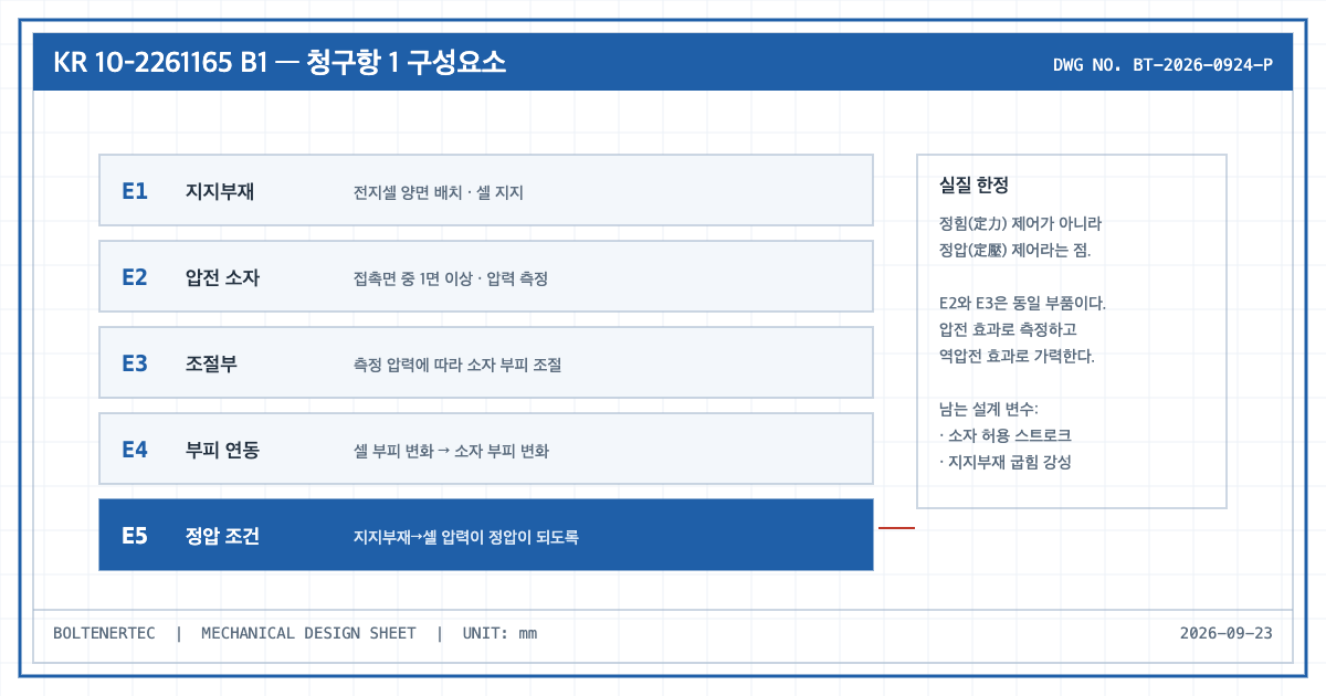
Claim 1 Element Comparison Table
| Element | Claim substance | Target equipment correspondence | Mechanical design impact |
|---|---|---|---|
| E1 Support member | Disposed on both sides of the battery cell to support the battery cell | Upper and lower pressure plates (first support part on the top face, second support part on the bottom face) | The bending stiffness of the plate is not limited. The surface pressure uniformity problem remains outside the claim scope |
| E2 Piezoelectric element | Disposed on at least one of the faces where the support member contacts the battery cell, measuring the pressure applied to the battery cell | A measuring element replacing the load cell position | The measuring element sits on the load path. Its stiffness is included in the series stiffness as it is |
| E3 Control part | Adjusts the volume of the piezoelectric element according to the pressure measured at that element | Controller | The force-applying element is not a separate cylinder but the measuring element itself. Sensor and actuator merge into one component |
| E4 Volume coupling | The volume of the piezoelectric element changes in accordance with the volume change of the battery cell | — | The cell swelling stroke must be absorbed by element displacement. The allowable displacement of the element becomes a design constraint |
| E5 Static pressure condition | The volume change of the piezoelectric element makes the pressure applied from the support member to the battery cell a static pressure | — | This is the substantive limitation. Constant pressure rather than constant force is the point of divergence from a conventional jig |
Mechanism-Perspective Analysis
The core of this claim is that E2 and E3 point to the same component. The piezoelectric element measures pressure through the piezoelectric effect and adjusts pressure by changing its volume through the inverse piezoelectric effect. The specification describes this as a first signal line (measurement signal) and a second signal line (drive signal). Merging sensor and actuator into one component reduces part count and accumulated assembly tolerance, but the measuring point and the force-application point are not physically separated, which makes cause and effect harder to distinguish inside the control loop.
From a mechanical design standpoint the real constraint is stroke. Whether the entire cell swelling displacement can be absorbed by the volume change of the piezoelectric element alone depends on cell thickness and expansion rate, and the claim does not limit the displacement range of the element. In practice this tends to become a two-tier configuration in which a conventional mechanism handles coarse adjustment and the piezoelectric element handles fine correction. In that case the backlash of the coarse adjustment mechanism and the pressure plate stiffness return as governing factors.
Some dependent claims limit the piezoelectric element to a cylindrical shape or to a plurality of elements. A plural arrangement touches on the direction of mitigating the pressure plate deflection problem through multi-point force application, but the claim language itself does not prescribe the arrangement pitch or the support span.
Items Requiring Confirmation
- The maximum displacement, allowable load and operating temperature range of the piezoelectric element are not limited numerically in the publication (undisclosed).
- Differences in wording between the granted claims (KR 10-2261165 B1) and the published claims (KR 10-2019-0124040 A) were not collated in this review. The table above is based on the published specification.
- The claim scope of the foreign family members (US11454556B2, EP3675272B1, CN111183547A) may differ by jurisdiction.
This article is a technical review based on a published patent publication number and does not judge whether any particular equipment infringes.
One-line summary: The substance of this patent is the shift from constant-force control to constant-pressure control, and the remaining design problems are the stroke of the piezoelectric element and the stiffness of the support member.
Source: Google Patents publications KR20190124040A / KR102261165B1.