Problem Definition
Compression preload is the initial clamping force that maintains inter-cell contact in a pouch-cell stack even as the cells expand in the thickness direction during charge-discharge. As SK On signed a five-year contract on August 27, 2026 to supply 9 GWh of LFP pouch battery cells to U.S.-based Neovolta Power from 2027 to 2031, demand for mass assembly of pouch cells at the ESS rack level is growing. Unlike prismatic or cylindrical cells, pouch cells have no metal can, so the cell itself is the only buffering structure against stack compression force. If initial preload is insufficient, cells shift microscopically during charge-discharge cycling, causing separator wear and electrode misalignment. Conversely, excessive preload concentrates localized stress on the pouch sealing area, creating an electrolyte leak path. The problem is how to numerically define the safety window between these two failure modes.
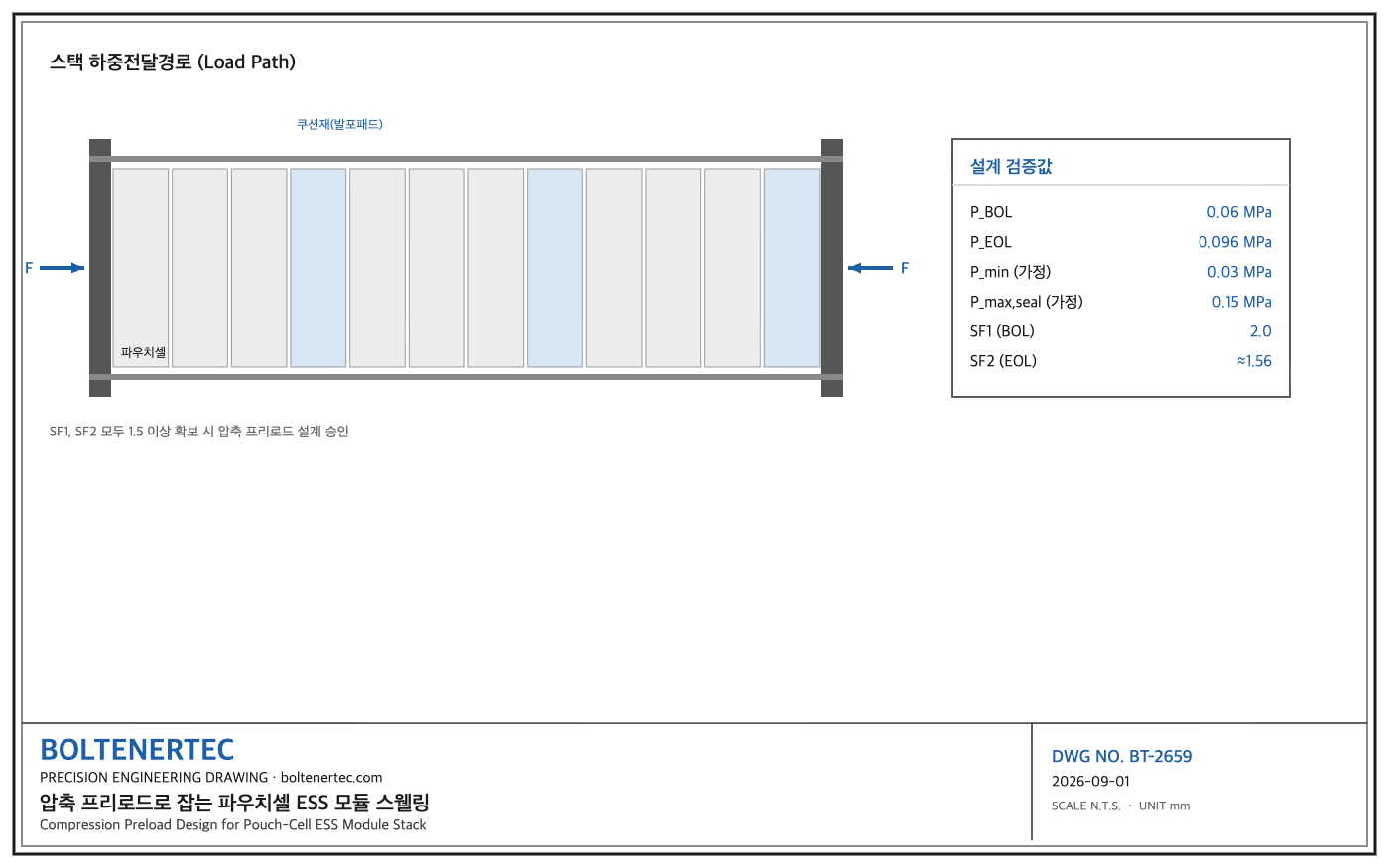
Kinematic Analysis
The pouch-cell stack forms a load path running from two end plates through tie rods to the cushioning material inserted between cells. Load begins at tie-rod tension, passes through end-plate bending, then cushion-material compression, and finally reaches the cell contact surface. In this path, the element with the lowest stiffness governs the effective spring constant of the whole stack. Cushion-material stiffness is typically one to two orders of magnitude lower than the cell’s own stiffness, so in practice the cushion material becomes the governing variable in preload design. Cells expand in the thickness direction as they charge from 0% to 100% SOC; the exact expansion rate must be confirmed from the cell manufacturer’s spec sheet as the BOL-to-EOL thickness change rate, and this calculation uses an example value as an assumption (confirmation needed).
Calculation / Formula Verification
Approximating the cushion material as a linear spring, the relationship between contact pressure and compression amount is as follows.
$$P = k \times \delta$$
Here, $P$ is contact pressure (MPa), $k$ is the cushion material’s compressive elastic modulus (MPa/mm), and $\delta$ is the compression amount (mm). The following values are assumed (linear approximation over the 40–60% strain range for a foamed silicone pad, confirmation needed): $k = 0.06$ MPa/mm, initial assembly compression $\delta_0 = 1.0$ mm, and additional compression from EOL swelling $\Delta\delta_{EOL} = 0.6$ mm (assuming a 3% EOL expansion rate based on a 20 mm cell thickness, confirmation needed).
$$P_{BOL} = 0.06 \times 1.0 = 0.06 \text{ MPa}$$
$$P_{EOL} = 0.06 \times (1.0+0.6) = 0.096 \text{ MPa}$$
Assuming a target minimum contact pressure of $P_{min} = 0.03$ MPa and an allowable maximum contact pressure at the sealing area of $P_{max} = 0.15$ MPa (a reference value for pouch-film seal strength, confirmation needed), the safety factor is verified doubly as follows.
$$SF_1 = \frac{P_{BOL}}{P_{min}} = \frac{0.06}{0.03} = 2.0$$
$$SF_2 = \frac{P_{max}}{P_{EOL}} = \frac{0.15}{0.096} \approx 1.56$$
$SF_1 \geq 2.0$ means there is no risk of preload deficiency at BOL, and $SF_2 \geq 1.5$ means sealing-area stress remains within the allowable range even at EOL. If both safety factors are 1.5 or above, the design is approved; if either falls short, the cushion-material stiffness $k$ or the initial compression $\delta_0$ is readjusted. In addition, the minimum value of $\delta_0$ must be recalculated by summing the accumulated assembly tolerances — tie-rod length tolerance, end-plate flatness, and cell thickness tolerance — using the root-sum-square (RSS) method to maintain the safety factor on the actual production line.
Shop-notes
- Machinability: the end plate is machined by flat milling from aluminum 6061-T6, and a flatness tolerance of 0.15 mm is achievable with a single CNC facing cut (tool vibration and cutting conditions should be confirmed on-site).
- Thickness-deviation control is the key issue for the cushion material; Thomson-press die-cutting is more advantageous than waterjet cutting for reducing thickness deviation.
- An alternative mechanism of inserting individual Belleville washer springs per cell was considered, but it was not adopted because the increased part count and assembly takt time make it inefficient for mass ESS rack production. The foamed cushion + tie-rod approach was adopted for its lower part count and ease of automation.
- When verifying prototypes with 3D printing (PETG), orient the print layer direction (Z-axis) perpendicular to the load direction, and add a 0.3 mm margin to the design dimensions to account for print tolerance (typically ±0.2 mm). PETG shrinkage is reportedly around 0.3–0.8% (confirmation needed), but precision fit interfaces should be re-verified on the final metal-machined part.
One-Line Summary
For pouch-cell ESS module compression preload, both the BOL-based SF1 and the EOL-based SF2 must be doubly verified at 1.5 or above to simultaneously prevent swelling and seal failure.
Design-Reflection Checklist
- [ ] Confirm BOL/EOL thickness change rate from the cell manufacturer’s spec sheet
- [ ] Obtain measured data for cushion-material compressive elastic modulus
- [ ] Recalculate SF1 and SF2, each at 1.5 or above
- [ ] Re-review the minimum value of δ0 after RSS-summing assembly tolerances
- [ ] Reflect print-layer direction and shrinkage margin when 3D-printing prototypes