A fluid-expansion probe sets its contact force from pressure and area regardless of stroke, but in exchange the bonded seam of its covers becomes the weakest point of the load path. US12046939B2 (applicant Wonik PNE Co Ltd; priority 2021-11-15; filed 2021-12-08; granted 2024-07-23) claims an expansion member for a charge/discharge probe in which a first cover and a second cover are bonded to form a fluid accommodation space, and a penetration hole is formed on top of the junction region surrounding that space. This post calculates the contact force and seam load of the expansion member to review its design margin.
1. Problem definition — where does pneumatic pressing fail?
With mechanical spring pressing, force changes when stroke changes. With a fluid-expansion member, force stays constant as long as supply pressure is constant. It is insensitive to cell thickness variation. But internal pressure also acts to peel the two covers apart. If the junction region also carries a penetration hole, the effective seam width shrinks. So is the design margin on the contact-force side or on the seam side?
The specification gives air, a non-conductive gas, as an example fluid and states that the expansion member may be made of an elastic material. Supply pressure and cover material grade are not stated.
2. Kinematic analysis — claim elements
| Element | Claim 1 feature | Mechanical interpretation |
|---|---|---|
| E1 | First fluid accommodation part that expands when fluid enters | Pressure → force converter |
| E2 | Fluid supply pipe with inflow/outflow path | Pressure-source connection |
| E3 | First and second covers bonded to form the space | Membrane structure |
| E4 | First junction region surrounding the space | Seal and structural seam |
| E5 | Penetration hole on top of the junction region | Section loss in the seam |
An inflated membrane has curvature. Membrane tension is proportional to the radius of curvature, and that tension opens the seam. The penetration hole locally reduces seam width.
3. Calculation — contact force and seam tension
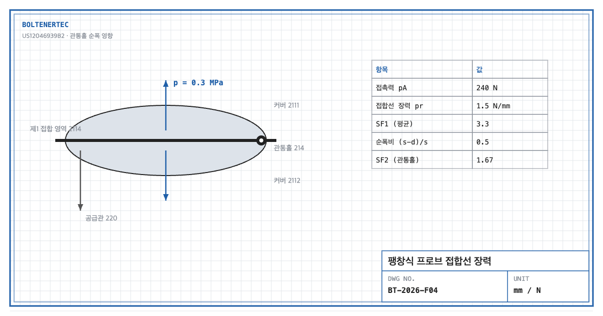
Design assumptions (to be reconfirmed by field measurement): supply pressure $p$ = 0.3 MPa, effective pressing area $A$ = 20 × 40 mm, inflation radius $r$ = 5 mm, seam width $s$ = 4 mm, hole diameter $d$ = 2 mm, seam peel strength $q_{allow}$ = 5 N/mm.
$$F_c = pA = 0.3\times 800 = 240\ \mathrm{N}$$
A 240 N contact force holds even when cell thickness varies by several millimeters. With a spring, stroke variation would become force variation.
$$N = p\,r = 0.3\times 5 = 1.5\ \mathrm{N/mm}$$
Here $N$ is membrane tension per unit seam length (N/mm).
$$SF_{1}=\frac{q_{allow}}{N}=\frac{5}{1.5}=3.3$$
At the hole, seam width drops to $(s-d)/s$ = 0.5. If peel strength is proportional to width, the local margin is:
$$SF_{2}=SF_{1}\times\frac{s-d}{s}=3.3\times 0.5=1.67$$
The average margin of 3.3 falls to 1.67 around the hole. Considering fatigue from repeated inflation, the hole edge becomes the first peel origin. Doubling the radius of curvature doubles the tension, so a design change that widens the expansion space directly erodes the seam margin.
4. Shop-notes
- Widen the seam around the hole. Widen the seam to $s+d$ only where the hole sits so the net width stays 4 mm. This adds less envelope than widening the whole seam.
- Machinability. Forming the hole before bonding damages the seam less than punching after bonding. For heat-sealed seams, extend the sealed area at least 1 mm beyond the hole edge.
- Pressure upper-limit control. If a regulator setting error doubles the pressure, $SF_2$ becomes 0.83. Fit a relief valve on the supply line opening at 1.2× the set pressure.
- Alternative mechanism — spring-loaded probe. No seam failure risk. Not adopted because: cell thickness variation becomes contact-force variation, requiring spring changes for mixed cell types.
5. Design checklist
- Were contact force ($pA$) and seam tension ($pr$) calculated separately?
- Is a local factor $SF_2$ ≥ 1.5 secured on the net width at the hole?
- Is the relief-valve opening pressure set for abnormal pressure rise?
- Are seam fatigue test conditions defined by the number of inflation cycles?
Items requiring confirmation
- Supply pressure, cover material, bonding method and hole size are not stated in the specification. All figures here are assumptions.
- The function of the hole in the specification (fixing, locating, etc.) should be reconfirmed in the original text. The KR family number is unconfirmed.
One-line summary: The seam margin of an expansion probe averages 3.3 but drops to 1.67 at the penetration hole, so widening the seam around the hole comes first.
Source: US12046939B2, “Expansion member for probe for charging and discharging battery and probe including the same”, claim 1 and specification (fluid type and elastic material).