For the fork-spacing load cells of a roll direct-docking AGV, sensing performance is decided less by sensor resolution than by friction on the fork guide surfaces. KR102171461B1 “Roll direct docking automatic guided vehicle” (applicant Cowintech Co., Ltd.; filed and prioritized 2020-05-22; granted 2020-10-29) claims a spacing-maintaining unit that holds a pair of forks at a set spacing, with a pair of X-axis displacement load cells that sense the moving pressure generated when the forks move. The forks also carry a load cell that senses clamp gripping pressure. This post calculates fork stiffness and the ratio of load-cell signal to friction noise.
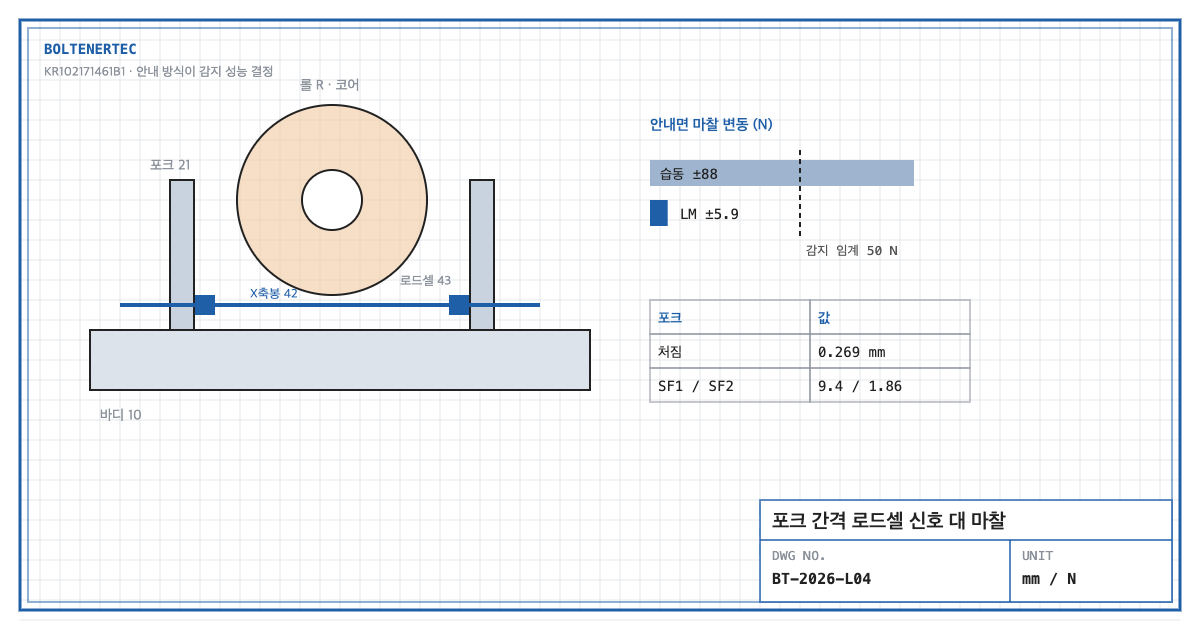
1. Problem definition — what is the load cell measuring?
The specification says the X-axis load cell senses “moving pressure, that is, pressure generated according to moving speed”. When the X-axis rod pushes the forks, the force on the load cell always includes the friction needed to move the forks. The reaction when a fork touches the roll core is a small signal riding on top. So if friction exceeds the signal, can the load cell distinguish contact?
2. Kinematic analysis — claim elements
| Element | Claim 1 feature | Mechanical interpretation |
|---|---|---|
| E1 | Pair of forks 21 moving horizontally on body 10, liftable roll transfer unit 20 | Two cantilever forks |
| E2 | Clamp 30 on top of the fork, chucking the roll core | Core gripper |
| E3 | Spacing unit 40: drive 41, X-axis rod 42, X-axis displacement load cells 43 | Pinion-rack drive + force sensing |
| E4 | Motion sensor 211 and gripping-pressure load cell 212 on the fork | Grip pressure vs. lift height |
| E5 | Traveling unit 50 | Moves to the supply turret |
The specification describes pinion 411 meshing with one face of the X-axis rod, buffer pad 32 on the clamp body to protect the core, and tilting module 53 that follows floor flatness. Roll weight and dimensions are not stated.
3. Calculation — fork deflection and signal-to-friction ratio
Design assumptions (to be reconfirmed by field measurement): roll mass 400 kg ($P$ = 1,962 N per fork), fork overhang $L$ = 300 mm, section 60 × 40 mm, S45C (elastic modulus 205,000 MPa, yield 345 MPa).
$$\delta=\frac{P L^{3}}{3EI}=\frac{1{,}962\times 300^{3}}{3\times 205{,}000\times 320{,}000}=0.269\ \mathrm{mm}$$
$$\sigma=\frac{P L}{b h^{2}/6}=\frac{588{,}600}{16{,}000}=36.8\ \mathrm{MPa},\qquad SF_{1}=\frac{345}{36.8}=9.4$$
With an allowable clamp alignment error of 0.5 mm (assumed), the deflection margin is:
$$SF_{2}=\frac{0.5}{0.269}=1.86$$
Fork stiffness is sufficient. The problem is on the load-cell side.
When a loaded fork moves in the spacing direction, guide friction is $F_\mu=\mu P$.
| Guide type | Friction coefficient (assumed) | Friction force | ±30% variation |
|---|---|---|---|
| Sliding plate | 0.15 | 294 N | ±88 N |
| LM guide (rolling) | 0.01 | 19.6 N | ±5.9 N |
With a core-contact detection threshold of 50 N (assumed), a sliding guide’s ±88 N friction variation exceeds the threshold, so contact cannot be distinguished from friction. With an LM guide the signal is 8.5 times the ±5.9 N variation. Changing the guide type, rather than upgrading the load cell, decides sensing performance.
4. Shop-notes
- Zero the load cell in the loaded state. An unloaded zero shifts by the friction increase after the roll is loaded. Use the average during low-speed travel after loading as the baseline and judge contact reaction as a difference.
- Machinability. Two rows of LM guides on the fork guide surface need 0.02 mm mounting-surface parallelism. Face-mill the body top plate in one setup and machine the reference-side guide shoulder at the same time.
- Alternative mechanism — ball-screw spacing drive. A ball screw instead of pinion-rack reduces backlash and improves spacing accuracy. Not adopted because: high screw efficiency makes back-driving easy, and contact reaction leaks into the drive, blurring the load-cell path. Self-holding would require an added brake.
- Safety. The spacing adjuster is a crush zone between the two forks. Provide an interlock that prohibits entry to the roll loading area while spacing moves.
5. Design checklist
- Were fork strength $SF_1$ and deflection $SF_2$ checked separately?
- Were loaded guide friction and its variation calculated?
- Is the contact detection threshold sufficiently larger than the friction variation?
- Is the load-cell zero referenced to the loaded state?
- Is crush protection at the fork spacing adjuster included?
Items requiring confirmation
- Roll mass, fork dimensions and guide type are not stated in the specification. All figures here are assumptions.
- The wording of claim 1 and quoted specification passages should be reconfirmed against the original publication (KIPRIS).
One-line summary: Fork-spacing load cells are buried in the ±88 N friction variation of a sliding guide, so sensing performance must be secured by adopting LM guides, not a better sensor.
Source: KR102171461B1, “Roll direct docking automatic guided vehicle”, claim 1 and specification (spacing unit, buffer pad, tilting module).