A winder is the machine that takes a long electrode strip, already coated and pressed, and rewinds it into a single roll while pulling it with a steady force.
- A winder pulls the electrode strip at a steady tension1 and winds it onto a roll. The roll keeps growing as it fills.
- To hold the same tension, the motor has to supply more torque2 as the roll gets bigger. With the assumed values in this post, 1.9 N·m becomes 15 N·m, about 7.9 times more.
- The work the motor does, its power3, stays at 83 W from start to finish. The force grows because the shaft turns more slowly.
The roll keeps changing while it winds
After the coater4 applies and dries the active material, the electrode strip is wound up at the end of the machine. It is wound again after the roll press5. The machine that does the winding is the winder, and the one that feeds the strip out is the unwinder. They stand at the two ends of a line and keep the strip flowing without a break.
It is easy to picture thread on a spool. An electrode strip behaves differently. It is powder material spread on thin metal foil, so pulling too hard stretches or tears it, and pulling too loosely lets the edge of the roll slump. The acceptable range of force is narrow, so a winder has to keep adjusting that force for as long as the roll grows. The motor and a sensor share that job.
Think of winding a roll of paper towels. The first turn around the tube is short and the last turn is long. You pull with the same force, yet the effort at your wrist rises as the roll gets bigger.
A loose paper roll still holds its shape. An electrode roll can crush its inner layers or slip sideways, so the winding force is set separately for each stage.
Unwinding runs in the opposite direction. On an unwinder the roll shrinks, so the torque needed for the same tension falls and the shaft spins faster. Read the winding calculation backwards and you have the unwinding calculation.
The cylinder at the center of the roll is the core6. At the start the roll is only as thick as the core. Each layer adds twice the strip thickness to the diameter. One layer is invisible, but with the assumed values about 2,600 layers pile up before the diameter reaches 7.9 times the core.
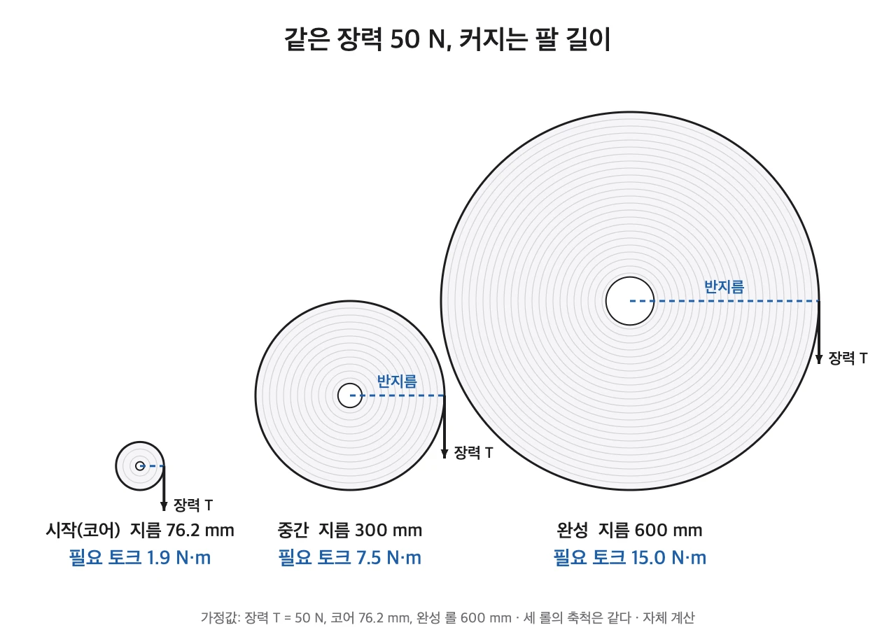
Torque is force multiplied by distance. Tension is the force pulling the strip, and it acts at the surface of the roll, so the distance is the roll radius. When the radius grows, the torque on the shaft grows in the same proportion. That is why 1.9 N·m near the core keeps climbing as the roll fills.
The numbers are more extreme than they look
First, the values behind the calculation. I set the core outer diameter at 76.2 mm and the full roll at 600 mm. Total electrode thickness is 0.100 mm, tension is 50 N and line speed is 100 m/min. All of these are assumed values chosen for explanation. They are not the specification of any machine, and real values must be rechecked after measurement on site.
A strip length of 2.78 km means one roll takes about 27.8 minutes to wind at 100 m/min. A torque ratio of 7.9 is a signal to size the motor for the full roll, not for the core. Power staying at 83 W leads to a plain consequence: the shaft slows down as the roll fills.
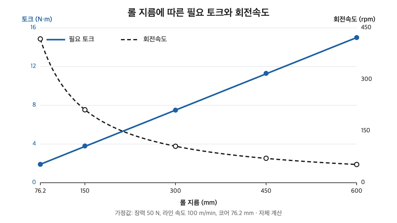
Figure 2 overlays torque and rotation speed against roll diameter. Torque rises along a straight line and speed falls along an inverse curve. The X those two lines make is the operating condition of a winder motor.
| Roll diameter (mm) | Strip length (m) | Share of total (%) | Torque (N·m) | Speed (rpm) |
|---|---|---|---|---|
| 76.2 (core) | 0 | 0.0 | 1.9 | 418 |
| 150 | 131 | 4.7 | 3.8 | 212 |
| 300 | 661 | 23.8 | 7.5 | 106 |
| 450 | 1,545 | 55.5 | 11.3 | 71 |
| 600 | 2,782 | 100.0 | 15.0 | 53 |
The speed column moves the other way. The line runs at the same 100 m/min, yet the shaft turns 418 times a minute near the core and 53 times when the roll is full. Just after a roll change the shaft is at its fastest. If the core and chuck sit off the rotation center, that error shows up first in this fast starting phase. As the roll grows, mass goes up and speed comes down, so each stage asks for attention in a different place.
The 300 mm row shows the gap between diameter and length most clearly. A roll at half diameter carries only about a quarter of the strip. The other three quarters wind on in the outer band from 300 mm to 600 mm. Torque grows in proportion to diameter, while length grows close to the square of it, so the two columns climb at different speeds. From the 150 mm row to the 300 mm row, torque doubles from 3.8 to 7.5 N·m, and length grows about five times, from 131 m to 661 m.
A roll that has reached half its size holds about half of the strip.
At half the diameter the roll holds about 23.8% of the final length, because length grows close to the square of diameter.
Double the diameter and the cross-section area becomes four times larger. Once the area taken by the core is subtracted it is not exactly four, which is why the table shows 23.8%. Estimating the remaining time from the diameter scale alone gives a badly wrong answer. With these assumed values, reaching 300 mm takes about 6.6 minutes and the remaining band takes about 21.2 minutes.
The numbers a designer looks for first
When I open a winder drawing, I look for the core diameter and the maximum roll diameter before the motor capacity table. Torque follows the ratio of those two numbers. Choose a motor from the core condition alone and, with these assumed values, the end of the roll needs 7.9 times as much torque. That is why I read those two numbers first.
Boltenertec, designing R2R equipment since 2005
That judgment comes from designing equipment that handles strips, such as roll presses, slitters and coaters. The machines differ in layout, but the torque in the winding section is calculated with the same formula.
One more point about tension. If the roll is wound at constant tension, the outer layers keep adding pressure on the inner layers. To reduce this, some plants lower the tension step by step as the roll grows, a method called taper tension7. The amount of reduction depends on the material, thickness and roll size, and no published value is confirmed here, so this post gives no number. It must be rechecked after measurement on site.
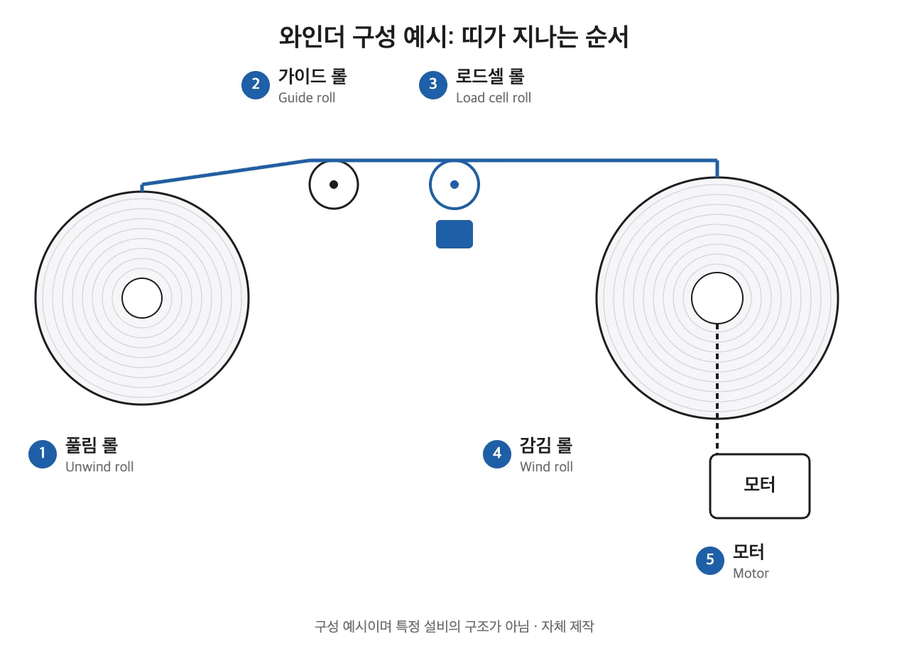
Tension cannot be seen, so a sensor reads it. A load cell8 converts the force of the strip into an electrical signal, and that value becomes the reference for adjusting motor torque. The control method itself is outside the scope of this post and needs separate review. On the mechanical side, the job is to keep the sensing roll aligned and its own rotating resistance low.
Suppose the core is changed from 76.2 mm to 152.4 mm. The diameter ratio falls from 7.9 to 3.9. Torque near the core rises from 1.9 to 3.8 N·m, so the torque range narrows. The strip length on the same 600 mm roll drops from 2.78 km to 2.65 km, about 5% less. A single core dimension moves both the torque range and the roll length. The actual core size is set by the line and the customer specification.
The moment of swapping a full roll for a new core is also part of the design. If a roll takes about 28 minutes to fill under these assumptions, a long swap means the line stands still or needs a device to buffer the strip. Swap methods differ from machine to machine, so this post does not pick one. I write the swap time on the drawing as a number. The space to pull out a roll and insert a new core is hard to enlarge once the layout is fixed.
A winder is a machine where hands can be caught between the moving strip and the roll. Covers and emergency stops that meet the pinch-point rules of the Korean Occupational Safety and Health Act go onto the drawing in the first stage, and the roll-change access path is fitted after them. If the order is reversed, cover positions collide with the maintenance path and are hard to fix later.
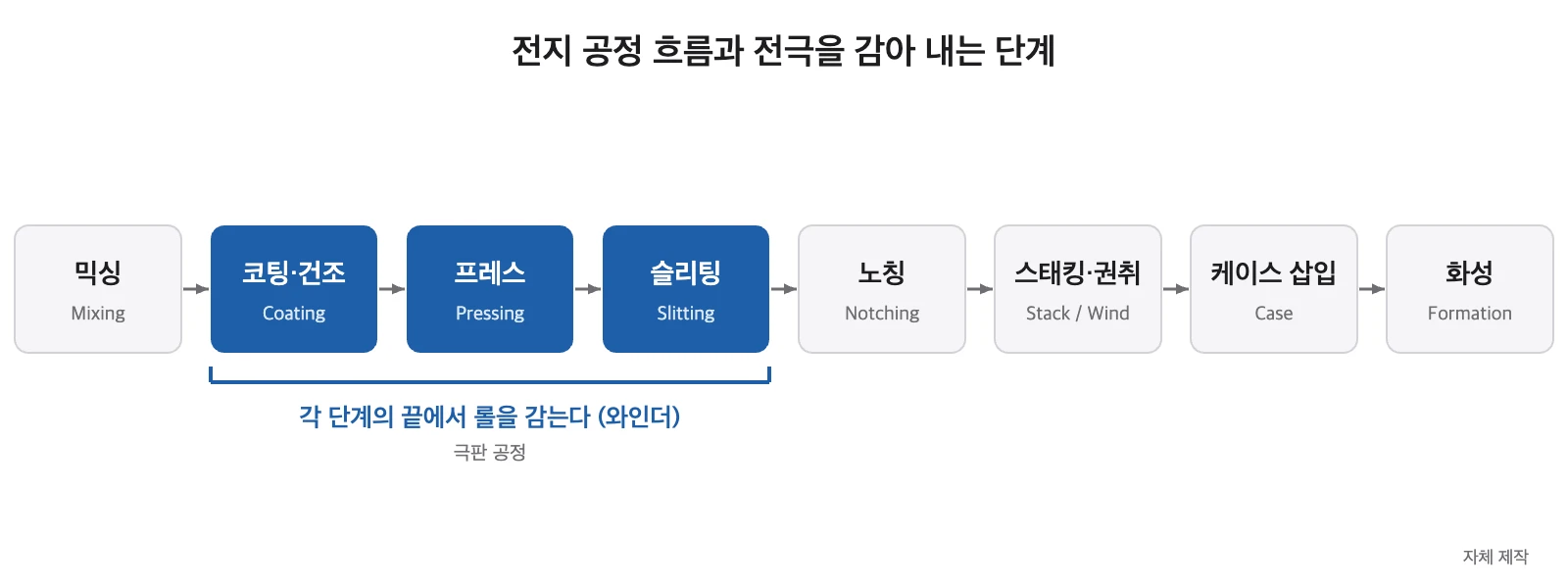
In the electrode process, winding and unwinding points follow one another. A roll is made at the end of the coater, the roll press and the slitter, and the same calculation repeats at each stage. The blue band in Figure 4 marks those positions.
If you are preparing for a career in this field, remember that this is a basic calculation in winder design work. I use AutoCAD and Autodesk Inventor for design, and I check engineering calculations like this one with tools I wrote in Python. Because length and torque follow from diameter and thickness alone, building the table yourself is good practice and gives you something concrete to explain in an interview. If you are only curious, understanding the middle row of the table is enough.
One step further, for engineers
The strip length $L$ is the wound cross-section area divided by the strip thickness.
$$L=\frac{\pi\,(D^{2}-d^{2})}{4\,t}$$$L$: strip length (mm), $D$: roll outer diameter (mm), $d$: core outer diameter (mm), $t$: total electrode thickness (mm).
$$M=\frac{T\cdot D}{2\times 10^{3}}$$$M$: torque to hold tension (N·m), $T$: tension (N), $D$: roll outer diameter (mm). With the assumed $T=50$ N and $D=600$ mm, $M=15.0$ N·m.
$$P=T\cdot v$$$P$: power (W), $T$: tension (N), $v$: strip speed (m/s). 100 m/min is 1.667 m/s, so $P=83$ W.
The safety factor was checked at two values. At a safety factor of 1.5 the required torque is 22.5 N·m, and at 2.0 it is 30.0 N·m. Both factors are my assumptions, and the applicable standard or in-house criterion must be confirmed. This calculation covers only the torque to hold tension. It excludes acceleration inertia torque and bearing friction torque, so it cannot be used as is for motor selection. Recheck after measurement on site.
For machinability, machining the core chuck seat and the shaft bearing seats in one setup, coaxially, is the better choice. A split-assembly shaft is an alternative, but stacked assembly tolerance increases rotational runout, so I did not adopt it. A surface-driven method, where a contact roll sets the surface speed and reduces the change in rotation speed, was also excluded in this case because it puts contact load on the coated surface. That exclusion is my design judgment.
Related posts (Korean): Prismatic cell high-speed winding at 7.5 cells/min is limited by web acceleration, Patent analysis of a cylindrical cell winding gripper
Winder design starts from two diameters. Once you know the core and the full roll, length, torque and winding time all come from the same formulas. The table here was built from assumed values, so it becomes the table of a real machine only after you rerun it with values from that machine.
Glossary
- Tension: the force pulling a strip along its length. Measured in N. ↩
- Torque: the force that tries to turn a shaft, found by multiplying force by the distance to the center of rotation. Measured in N·m. ↩
- Power: work done per unit of time, found by multiplying force by speed. Measured in W. ↩
- Coater: a machine that spreads active-material slurry on metal foil at a set thickness and dries it. ↩
- Roll press: a machine that passes coated electrode between two rolls to set its thickness and density. ↩
- Core: the cylinder fitted at the center of a roll. The electrode strip winds onto it. ↩
- Taper tension: a method of lowering the winding force step by step as the roll grows, to reduce crushing of the inner layers. ↩
- Load cell: a sensor that converts an applied force into an electrical signal. ↩
Sources
- Own calculation. Core outer diameter 76.2 mm, roll diameter 600 mm, total electrode thickness 0.100 mm, tension 50 N and line speed 100 m/min are all assumed values for explanation and not the specification of any machine.
This post is meant to help readers understand industry and technology. It is not a recommendation to buy or sell any stock.