Problem Definition
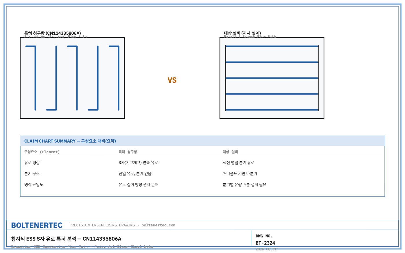
CN114335806A is a Chinese patent concerning the coolant flow-path structure of an immersion-cooled ESS battery box, and it is prior art that must be reviewed when designing immersion-cooling ESS equipment. The applicants are NR Electric Co Ltd and its affiliate Changzhou NR Electric Power Electronics Co Ltd, with a filing date of December 31, 2021, and a publication date of April 12, 2022 (source: Google Patents, publication number CN114335806A). A request for substantive examination was filed on October 25, 2024, and the application is currently pending, with only one confirmed family filing to date, in China (CN). The core claim of this patent is a structure that connects the flow paths between battery modules in series to form an S-shaped flow path. Unlike our own previously covered sealing design (bolt clamping, O-ring), this patent addresses the design of the flow path itself.
Kinematic Analysis
The core elements of claim 1 are: (a) a box body and cover, (b) flow paths formed between adjacent modules and between a module and the side wall, (c) an S-shaped passage formed by sequentially connecting these flow paths, and (d) a flow sequence entering the S-shaped passage from the inlet, passing through the upper and lower sections of the modules, and exiting through the outlet. Claim 4 specifies a structure that alternately places partitions (separating chambers) behind odd-numbered modules and in front of even-numbered modules to force the S-shaped flow. Claim 5 specifies a bottom-cooling structure in which bosses (protrusions) on the box floor create flow-path grooves beneath the modules. Because the flow paths are connected in series, this structure has fewer parts, but it carries the structural limitation that coolant temperature rises progressively toward the last module, which can create cooling deviation between modules.
Calculation / Formula Verification
Instead of a quantitative calculation, verification here is performed as a claim chart mapping the claim elements one-to-one against our own design (based on the previously covered sealing design article).
| Claim Element (CN114335806A) | Correspondence to Target Equipment | Note |
|---|---|---|
| Box body + cover plate, inlet/outlet on side wall | Corresponds (similar) | Our design also adopts the same basic structure |
| Flow paths between modules and between module-sidewall connected sequentially in S-shape | Does not correspond | We reviewed a parallel branched flow path (not series) |
| Alternating partitions on odd/even modules forcing S-shaped flow | Does not correspond | Parallel structure means a different partition arrangement |
| Floor boss forming flow-path groove (bottom cooling) | Partially corresponds | Bottom-cooling concept is similar, but boss shape differs |
| Cover sealing groove + sealing ring (claim 9) | Corresponds (similar) | Conceptually identical to the O-ring groove in the previously covered sealing design article |
A series flow path has a longer total flow length and therefore greater pressure loss, but fewer parts; a parallel flow path has shorter branch lengths and therefore lower pressure loss, but additionally requires an orifice design to prevent uneven flow distribution. Quantitative flow-rate/pressure-loss calculations are excluded from the scope of this analysis because coolant viscosity and flow-rate specifications are not disclosed (confirmation needed).
Shop-notes
- Machinability note: claim 5’s floor-boss/flow-path-groove structure presupposes integral casting or integral machining with the box body. When manufactured by aluminum die-casting, boss-height deviation translates directly into flow-path cross-sectional-area deviation, so a two-step process — die-casting followed by separate cutting of only the flow-path floor surface — is advantageous for tolerance control.
- Alternative design and non-adoption reason: the claim’s S-shaped series flow-path approach was reviewed as an alternative for our own design, but a parallel branched flow path was adopted instead, because of the structural limitation that as module count increases, the last module’s coolant inlet temperature rises relative to preceding modules, widening the inter-module temperature deviation. The parallel structure carries the added burden of orifice design, but securing cooling uniformity as module count scales was judged more important.
- This patent is currently pending substantive examination, and whether it will be granted is not yet determined. Since the claim scope may be amended during examination, the grant status and claim-amendment history should be re-confirmed before finalizing the design.
- Infringement cannot be determined from this analysis alone. Although the claim-element correspondence table shows many non-corresponding items, the final determination must go through review by a qualified patent attorney.
One-Line Summary
CN114335806A’s S-shaped series flow path has fewer parts but carries the risk of inter-module cooling deviation; our design achieves differentiation with a parallel branched flow path that corresponds similarly to only 2 of the 5 claim elements.
Checklist
- Periodically check CN114335806A’s grant status and claim-amendment history
- Confirm whether CFD verification of the parallel branched flow path’s orifice design values has begun
- Request formal infringement-possibility review from a patent attorney
- Obtain measured tolerance data for the aluminum die-casting + cutting two-step process