Problem Definition
Immersion Cooling ESS is a cooling method that removes heat by directly submerging battery modules in dielectric coolant fluid. On August 26, 2026, GS Power unveiled its new ‘G.U. ESS’ product, announcing this method as a commercial product for data centers and microgrids. Unlike air- or liquid-cooling methods, the entire battery is submerged in coolant, so the module housing must withstand constant immersion. This creates a mechanical contradiction. The housing must be fully sealed to prevent coolant leakage, but it must also be periodically openable for cell degradation inspection or module replacement. How to quantitatively resolve this conflict between sealing integrity and maintainability is the design problem here.
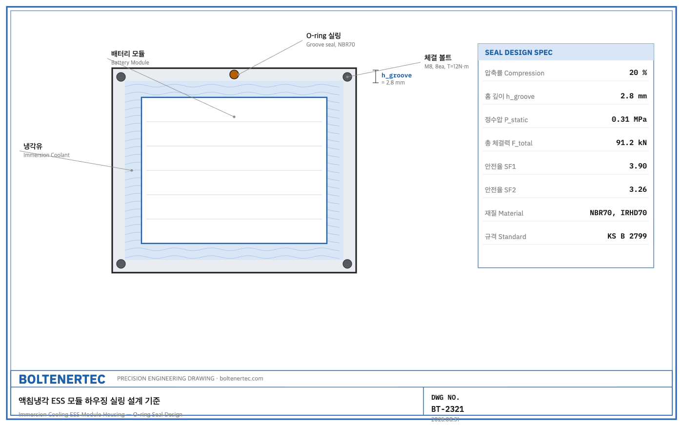
Kinematic Analysis
The housing’s sealing structure divides broadly into three load paths. First, hydrostatic pressure from the coolant’s self-weight acts on the housing floor and side walls. Second, flow pressure generated by the circulation pump adds to the sealing interface. Third, the O-ring undergoes repeated compression and relaxation with each maintenance cycle of opening and closing the cover plate, accumulating fatigue. Among these three paths, what governs the sealing design is not hydrostatic pressure but the balance between bolt clamping force and O-ring reaction force. Hydrostatic pressure itself is relatively low, but a separate design pressure must be defined once circulation-pump surge pressure and thermal-expansion pressure spikes are also considered.
Calculation / Formula Verification
The following design conditions are assumed (assumed values before field measurement; actual material specifications should be confirmed after field measurement). Module immersion depth h = 600 mm, coolant density ρ = 900 kg/m³ (a typical value for synthetic ester-based coolant, estimate), design pressure including circulation-pump differential pressure and surge margin P_design = 60 kPa (estimate), cover-plate area A = 0.8 m × 0.4 m = 0.32 m², O-ring seal perimeter L = 2,400 mm, and O-ring reaction force at 20% compression w = 30 N/mm (a typical elastomer compression reaction-force value, estimate).
Hydrostatic pressure: $$P_{static} = \rho g h = 900 \times 9.81 \times 0.6 = 4298.7\ \text{Pa} \approx 4.3\ \text{kPa}$$
Hydrostatic pressure alone is only 4.3 kPa, so the sealing design pressure takes circulation-pump surge pressure as the governing condition (P_design = 60 kPa). The sum of the pressure load acting on the cover plate and the O-ring reaction force is defined as the required clamping force.
$$F_{total} = P_{design}\times A + w\times L = (60000\times0.32)+(30\times2400) = 19200+72000 = 91200\ \text{N}\approx91.2\ \text{kN}$$
The O-ring reaction-force term (72 kN) accounts for 79% of the total required clamping force. In other words, this design is governed by the seal’s own elastic reaction force rather than the pressure load. 24 M8 bolts (fastener grade should be confirmed on-site; 8.8 grade assumed) are arranged around the perimeter at a 100 mm pitch, applying an allowable preload of 15 kN each.
$$F_{available}=24\times15\text{kN}=360\ \text{kN}$$
Primary safety factor: $$SF_1=\frac{F_{available}}{F_{total}}=\frac{360}{91.2}\approx3.9$$
As a secondary verification, an extreme condition is applied assuming surge pressure at twice the design pressure (120 kPa).
$$F_{total,surge}=(120000\times0.32)+72000=38400+72000=110400\ \text{N}\approx110.4\ \text{kN}$$
$$SF_2=\frac{360}{110.4}\approx3.26$$
Both conditions exceed the standard mechanical-design safety-factor benchmark of 2.0 (SF1=3.9, SF2=3.26), so the bolt-clamping design retains margin even under pressure-spike conditions. However, the fact that SF2 is 16% lower than SF1 indicates that surge-pressure variation is the variable that erodes clamping margin fastest. In actual application, the pump’s rated differential pressure must always be confirmed. The O-ring groove design targets a 20% compression ratio per KS B 2799. For an O-ring cross-sectional diameter of d=3.5mm, the groove depth is as follows.
$$h_{groove}=d\times(1-0.20)=3.5\times0.8=2.8\ \text{mm}$$
The groove width is designed as W = d×1.4 = 4.9mm, with machining tolerance managed at groove depth 2.8mm ±0.05mm and width 5.0mm (+0.1/-0).
Shop-notes
- Machinability note: the O-ring groove should be machined by CNC milling, and the corner radius must secure at least 0.5× the O-ring cross-sectional diameter (approx. 1.75 mm). Insufficient corner radius causes O-ring twist during assembly, resulting in localized sealing failure, so it is safer to machine the corners separately with a ball-end mill.
- Alternative design and non-adoption reason: a gasket (solid sealant sheet) approach was also considered. A gasket requires no groove machining, giving lower initial machining cost, but repeated exposure to dielectric coolant causes accumulated compression set, making it a consumable that must be replaced every maintenance cycle. The O-ring approach was adopted because its greater elastic recovery force results in a lower replacement frequency.
- Coolant expands thermally as temperature rises (estimated expansion coefficient around 0.0008/°C, to be recalculated once the material is finalized). When rising from room temperature 25°C to operating temperature 65°C, volume increases by approximately 3.2%, so an expansion tank or vent margin space must be secured at the top of the housing.
- Bolts must be re-torqued to the same value at every maintenance cycle to maintain the assumed 15 kN preload. A torque-management table must be included in the assembly process SOP.
One-Line Summary
The immersion-cooling ESS housing seal is governed not by hydrostatic pressure but by O-ring reaction force, and bolt-clamping safety factors of SF1 3.9 and SF2 3.26 must be verified up to surge-pressure conditions to secure maintainability and sealing integrity simultaneously.
Checklist
- Obtain inspection reports for O-ring groove machining tolerance (depth 2.8mm±0.05, width 5.0mm+0.1/-0)
- Confirm the calibration interval of the torque wrench used to manage 15 kN bolt preload
- Reflect coolant expansion-tank margin volume (3.2% or more) in the drawing
- Re-verify calculated values after field-measuring actual coolant density and expansion coefficient