A thermal-runaway propagation barrier is a structure inside an ESS rack that prevents one module’s thermal runaway from spreading to adjacent modules. The 2026 edition of NFPA 855 elevated this concept to a performance standard. Where the 2023 edition focused on response and damage mitigation after a fire occurred, the 2026 edition requires an outcome-based standard: “thermal runaway must not propagate to adjacent cells/modules.” UL9540A full-scale fire testing has also been elevated from the cell/module level to the rack/system level.
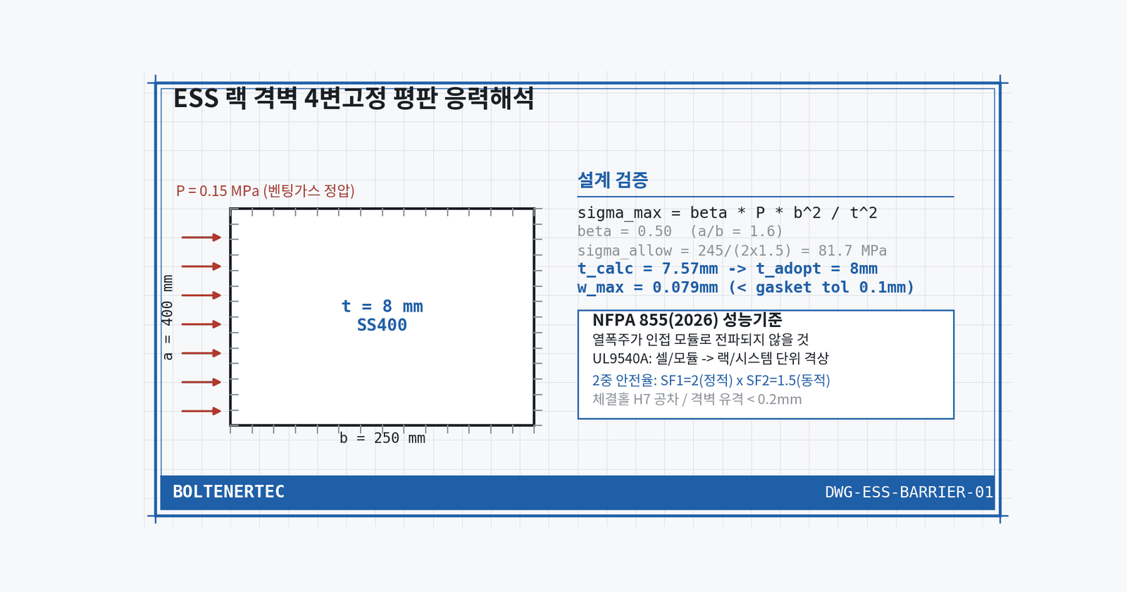
Problem Definition
The barrier must simultaneously withstand two conflicting loads. One is the static pressure of venting gas from a thermal-runaway cell; the other is the flame and pressure wave of an adjacent fire. Making it thicker increases stiffness but blocks the venting-gas discharge path, increasing the risk that cell internal pressure exceeds the barrier’s rupture strength. Enlarging the vent opening, conversely, opens a flame-propagation path. Skipping quantitative calculation leads to redesign at the certification-testing stage.
Kinematic Analysis
The barrier is approximated as a rectangular flat plate fixed on all four edges. The load is assumed to be venting-gas static pressure $P$ distributed uniformly across the plate surface. The standard module barrier dimensions are set at $a=400$mm, $b=250$mm (estimated; basis: proportional sizing to the standard module width of a 20-foot containerized ESS rack). The instantaneous venting-gas pressure is set at $P=150$kPa (estimated; basis: reference to the upper bound reported in UL9540A full-scale test cases). The material is assumed to be SS400 (yield strength 245MPa).
Calculation / Formula Verification
The maximum stress of a rectangular flat plate fixed on all four edges is as follows.
$$\sigma_{max} = \beta \cdot \frac{P \cdot b^2}{t^2}$$
$P$ is the load (MPa), $b$ is the short side (mm), $t$ is the thickness (mm), and $\beta$ is a coefficient depending on the $a/b$ ratio. At $a/b=1.6$, $\beta \approx 0.50$ is applied. The safety factor is dually verified: a static safety factor $SF_1=2$ is multiplied by a dynamic coefficient $SF_2=1.5$ that reflects the instantaneous-pressure characteristic of venting gas.
$$\sigma_{allow} = \frac{245}{2 \times 1.5} = 81.7 \text{MPa}$$
Back-calculating the required thickness.
$$t = \sqrt{\frac{\beta \cdot P \cdot b^2}{\sigma_{allow}}} = \sqrt{\frac{0.5 \times 0.15 \times 250^2}{81.7}} = 7.57 \text{mm}$$
Applying standard plate-stock gauge, the thickness is finalized at $t=8$mm. Deflection is also checked.
$$w_{max} = \alpha \cdot \frac{P \cdot b^4}{E \cdot t^3}$$
Substituting $\alpha \approx 0.0138$ ($a/b=1.6$) and $E=200{,}000$MPa gives $w_{max}=0.079$mm. This deflection is within the adjacent sealing-gasket assembly tolerance ($\pm0.1$mm), meaning barrier deflection does not affect sealing performance.
Shop-notes
- Finalized design: 8mm SS400 flat plate, fastened with 4-edge fixed brackets. Venting-gas discharge is separated into a dedicated upper duct rather than the barrier, so the barrier handles only its pure blocking function.
- Alternative mechanism (not adopted): 5mm thickness + rib-reinforcement design. Reason: if rib-intersection weld seams are directly exposed to flame, localized strength reduction occurs, and full on-site weld-defect verification is difficult.
- Machinability note: 8mm SS400 plate can be used after laser cutting without separate heat treatment, roughly 30% lower machining cost than the rib-reinforcement design. Fastening holes must be held to H7 tolerance to keep barrier assembly play within 0.2mm.
- Unconfirmed BOS-related variables such as the exhaust fan should be confirmed after field measurement.
Design-Reflection Checklist
- 8mm barrier thickness applied
- Fastening-hole H7 tolerance reflected
- Venting-gas duct separated from barrier function
- UL9540A rack-level test schedule aligned with prototype delivery
One-Line Summary
Meeting NFPA 855 (2026) performance criteria cannot pass certification without quantitative verification at the level of 8mm barrier thickness and 0.079mm deflection.