Problem Definition
The busbar joint is the point with the highest risk of electric shock or pinching injury in a battery module assembly line. In a structure where the busbar is bolted to the terminal, the terminal surface remains energized right up until the moment of fastening, and contact by a worker’s finger or a robot gripper can lead to a short-circuit accident. In ESS/EV modules where high-voltage and miniaturization are advancing simultaneously, the gap between adjacent module terminals also narrows, compounding the problem. GM Global Technology Operations LLC’s US patent US11,621,462B2 (filed 2021-02-12, granted 2023-04-04, family DE102021131847A1, CN114927836B) solves this problem with an insulating cap and a window structure in the terminal jacket.
Claim Element Comparison (Claim Chart)
| Claim 1 Element (US11,621,462B2) | Boltenertec Standard ESS Module Busbar Joint Design |
|---|---|
| Electrochemical battery cell | Pouch/prismatic cell stack (common) |
| Electrical terminal having a contact surface | ICB busbar contact plate (common structure, material may differ between copper/aluminum) |
| Screw nut fastening the terminal to the connector | Generally bolt + torque wrench fastening (common, but whether the nut is integrated varies by design) |
| Insulating cap attached to the nut | Core differentiator of this patent. Conventional designs typically add a separate insulating cover afterward or omit it |
| Terminal jacket window surrounding the cap with a 3–8 mm gap, exposing the contact surface while blocking finger passage | Core differentiator of this patent. A numerically defined gap design is not codified in domestic standard designs (confirmation needed) |
Calculation / Formula Verification
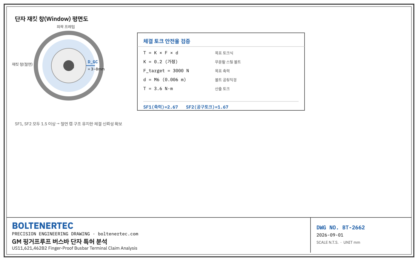
The patent specification states that the radial gap $D_{GC}$ between the jacket-window inner circumference and the nut-cap outer circumference is designed at 3 mm–8 mm, with a specific embodiment specifying 3.5 mm–5.5 mm, smaller than an adult little finger’s thickness. The narrower this gap, the greater the shock/pinch-prevention effect, but there is a trade-off in that bolt-fastening tool accessibility worsens, increasing assembly takt time. From a fastening-torque perspective, the safety factor is verified using the following relationship.
$$T = K \times F \times d$$
Here, $T$ is fastening torque (N·m), $K$ is the torque coefficient (assumed 0.2, a typical value for unlubricated steel bolts, confirm after field measurement), $F$ is the target axial force (N), and $d$ is the bolt nominal diameter (m). Applying a target axial force of $F=3000$N to an M6 bolt (assumed axial-force yield limit of approximately 8,000 N; material and grade to be confirmed), a required torque of $T = 0.2 \times 3000 \times 0.006 = 3.6$ N·m is obtained. The safety factor against yield axial force is verified doubly as follows.
$$SF_1 = \frac{F_{yield}}{F_{target}} = \frac{8000}{3000} \approx 2.67$$
$$SF_2 = \frac{T_{max,tool}}{T_{target}} = \frac{6.0}{3.6} \approx 1.67$$
$T_{max,tool}=6.0$N·m is an assumed value for the effective maximum torque a torque wrench can deliver inside the narrow jacket window (should be re-confirmed on-site depending on tool approach angle). If both safety factors are 1.5 or above, fastening reliability can be judged secured while retaining the insulating-cap structure.
Shop-notes
- Machinability: the patent’s overmolded integral jacket+cap structure creates an undercut in the injection mold, requiring a slide core. A two-piece snap-fit structure assembled after separate injection molding has lower tooling cost but adds one assembly step.
- An alternative mechanism of covering the entire terminal with a shutter-type cover instead of an insulating cap was considered, but it was not adopted because the shutter open/close mechanism adds part count and failure points. The patent’s window structure was prioritized for its higher protection effect relative to part count.
- To satisfy the Occupational Safety and Health Act’s pinch-prevention requirements, the gap must be re-reviewed against domestic adult finger dimension standards, and conformity with the relevant KS standard must be confirmed before adopting the patent’s 3–8 mm value as-is.
One-Line Summary
GM’s patent’s 3–8 mm insulating-gap structure is a design that numerically fixes the trade-off between fastening-tool accessibility and shock prevention, and the torque safety factor requires double verification at 1.5 or above.
Design-Reflection Checklist
- [ ] Re-review the insulating gap against domestic adult finger dimension standards
- [ ] Confirm measured yield axial force by bolt grade/material
- [ ] Field-measure the torque wrench’s effective maximum torque in the narrow space
- [ ] Recalculate SF1 and SF2 at 1.5 or above
- [ ] Compare cost between injection-mold slide core vs. two-piece assembly