The laser notching drum-type pattern jig is the key element in which a cylindrical rotating body wraps and supports the electrode film, determining the notching position.
Problem Definition
Domestic notching equipment makers are improving their equipment by combining laser notching and the winder in-line to boost productivity. However, as transport speed increases, the reaction force of the film tension wrapping around the drum also increases together. As the reaction force grows, the drum’s rotating shaft deflects, and once the shaft deflects, the notching position departs from the electrode tab’s allowable tolerance. When raising the notching speed, should shaft stiffness be reviewed first, or should tension be lowered first?
Kinematic Analysis
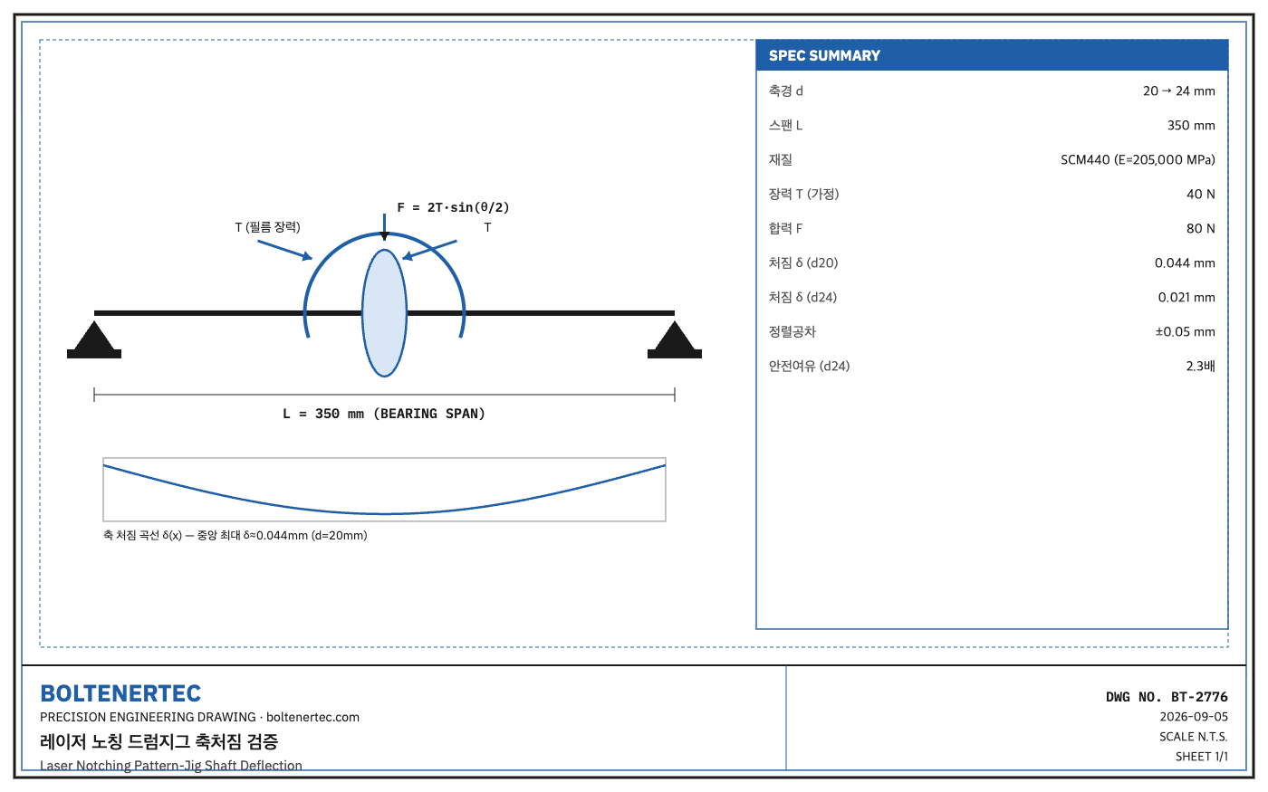
The pattern jig disclosed in KR102430493B1 (DA Technology, filed 2021-03-22, registered 2022-08-10) has a structure in which both ends of a cylindrical drum are rotatably connected to the jig base (Claim 1). Since the electrode film passes while wrapping around the drum’s outer surface at a certain wrap angle, the resultant force of the film tension acts on the drum in the radial direction. The rotating shaft supporting the drum can be approximated as a simply supported beam, and the larger the wrap angle, the larger the resultant force.
Calculation and Formula Verification
For wrap angle $\theta$ and film tension $T$, the resultant force $F$ acting on the drum is as follows.
$$F = 2T\sin\left(\frac{\theta}{2}\right)$$
If the wrap angle $\theta=180°$, then $\sin(90°)=1$, so $F=2T$. Taking the film tension as $T=40$ N (assumed value; re-confirmation required after field measurement), $F=80$ N.
The deflection for a central concentrated load on the shaft follows the simple-beam formula.
$$\delta = \frac{FL^3}{48EI}$$
For shaft diameter $d=20$ mm, bearing span $L=350$ mm, and material SCM440 ($E=205{,}000$ N/mm²), the second moment of area is as follows.
$$I = \frac{\pi d^4}{64} = \frac{\pi \times 20^4}{64} \approx 7854\text{mm}^4$$
Substituting this in, $\delta \approx 0.044$ mm. If the electrode tab alignment tolerance is taken as ±0.05 mm (per KS B ISO 286, separate confirmation against field drawings required), the deflection has already consumed about 88% of the tolerance. The practical implication is clear. This shaft is a design element governed by stiffness, not strength, and even a small addition of bearing wear or temperature change could exceed the tolerance.
If the shaft diameter is increased to $d=24$ mm, $I\approx16287$ mm⁴, and $\delta\approx0.021$ mm, a reduction. The safety margin relative to the allowable deflection is $0.05/0.021\approx2.3$x, satisfying a stiffness-based safety factor of 2 or more. Bending stress is also checked together. $M=FL/4=7000$ N·mm, $\sigma=Mc/I\approx5.16$ MPa, which has ample margin against SCM440’s yield strength, reconfirming that this design is governed by stiffness, not strength.
Practical Application (Shop-notes)
Increasing the shaft diameter from 20 mm to 24 mm also changes the bearing specification and coupling specification together, so a fillet radius of at least R2 at the shaft step must be secured to reduce stress concentration and heat-treatment distortion, ensuring machinability. As an alternative mechanism, reducing the bearing span from 400 mm to 250 mm and adding an intermediate support bracket was also reviewed, but was not adopted due to increased jig replacement time and interference with the dust collection unit. When pre-verifying the deflection trend with a 3D-printed (PETG) prototype jig, the design margin must account for the fact that the deflection value may be overestimated relative to the actual part, considering stiffness reduction depending on print orientation (approximately 20–30%, varying by material and print conditions) and print tolerance (approximately ±0.2 mm).
Design Reflection Checklist
- Calculate rotating shaft deflection and confirm safety margin against tolerance (target 2x or more)
- Re-review changed bearing/coupling specifications
- Secure fillet radius of R2 or more at the shaft step
- Account for print-orientation stiffness reduction and print tolerance when 3D-printing prototypes
One-Line Summary: The notching drum jig’s rotating shaft design is governed by stiffness, and securing a 24 mm shaft diameter yields a 2.3x safety margin.