The secondary-battery electrode notching process shears an ultra-thin polymer film to form electrode tabs, starting from the trade-off condition that excessive film tension causes rupture while insufficient tension degrades notching precision. Tech-I Co., Ltd.’s registered patent KR102002875B1 (application no. KR1020170168069A, filed 2017-12-08, granted/published 2019-07-23, inventor Cho Eun-seok) is a secondary-battery electrode notching system that solves this problem with dual servo drives and an intermittent-feed cam structure (source: Google Patents full text).
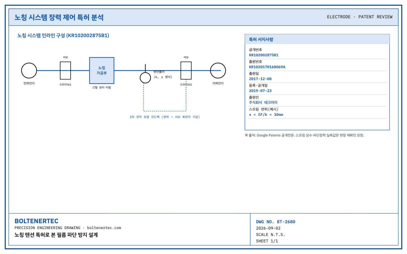
Patent Claim Mapping (Claim Chart)
| Claim 1 Element | Target Equipment Design Perspective |
|---|---|
| In-line arrangement of unwinder + notching section + rewinder | Identical to standard R2R notching line configuration |
| 1st/2nd film drive means (servo counter-roller pairs) | Dual servo drive before/after notching sets the input-rate reference value |
| Tension adjustment means (guide roller + tension roller + displacement sensor) | Dual tension control: 1st-stage mechanical buffering, 2nd-stage electronic correction |
| 1st/2nd feeding means (cam + cam rod + LM guide + feeding roller) | Intermittent stop-and-advance cycling achieves notch punching during continuous unwinding |
Kinematic Analysis
The core of this structure is that the tension roller, supported by a tension spring, rises and falls linearly according to film pressure to absorb tension in a first stage, overlaid with a second-stage electronic control that trims the downstream servo motor’s rotation angle per unit time when displacement deviates from the reference value. This structure reduces response delay compared to a purely mechanical damper approach, and the load-transfer path forms a closed loop: film tension → tension roller displacement → sensor signal → servo correction. The fact that follow-on patents citing this patent’s family (Uilee Enertech KR102667004B1, Haesung DS KR102500839B1, etc.) extend into roll-to-roll surface-pressure presses and electrode production systems also shows that this tension-control concept is being applied beyond the notching process to the press process in general.
Calculation Verification (Design Example, Assumed Values)
Taking the tension spring constant supporting the tension roller as $k = 0.5\text{ N/mm}$ (assumed value), the tension roller displacement for a film tension change of $\Delta F = 5\text{ N}$ is as follows.
$$x = \frac{\Delta F}{k} = \frac{5\text{ N}}{0.5\text{ N/mm}} = 10\text{ mm}$$
This displacement amount is exactly the stroke the sensor must detect, and in practice the gap between the high-tension and low-tension limit sensors should be designed with margin beyond this displacement value, at a safety factor of 2.0 or above, so that displacement within the normal range is never missed. The actual values of spring constant and film rupture tension should be confirmed after field measurement through tensile testing for each film material.
Shop-notes
As an alternative mechanism, inserting a load cell directly into the film path instead of a tension roller to measure tension in real time could be considered, but it was not adopted because contact friction and the added roller inertia could actually increase the risk of ultra-thin film rupture. Machinability note: if the alignment tolerance between the cam rod and the LM guide block is off, the feeding roller’s reciprocating trajectory becomes asymmetric, generating an instantaneous shock tension on the film during the intermittent-stop interval, so managing parallelism tolerance during assembly is the key machining challenge.
Design-Reflection Checklist
- Recalculate the tension roller’s spring constant and displacement range
- Secure a safety factor of 2.0 or above for the sensor-detection interval (high/low tension limits)
- Establish a parallelism-tolerance management standard for the cam rod–LM guide
- Obtain measured rupture-tension data for each film material (field measurement)
One-Line Summary
Notching tension control catches both rupture and slack only when the tension roller’s mechanical buffering overlaps with the servo’s electronic correction.