Problem Definition
The calender roll press rolls the positive and negative electrode sheets by passing them between two rolls. When the hydraulic cylinder applies a pressing force to the upper roll, pressure is distributed across the entire roll-to-electrode contact area. Unless the load per unit width — the line load (q) — is calculated, the rolling condition cannot be set quantitatively. Excessive line load causes roll surface indentation and local deflection, while insufficient line load causes the electrode density to fall short of the target value.
Kinematic Analysis
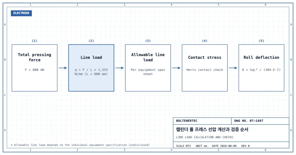
Cylinders are typically arranged at two locations, one at each end of the roll. It is assumed that the total pressing force $F$ is shared equally between the left and right cylinders. If the effective contact width of the electrode coating is $L$(mm), then under the simplifying assumption that pressure is distributed uniformly across the width direction, the line load is given by:
$$q = \frac{F}{L}$$
Here, $F$ is the total pressing force (N), $L$ is the effective contact width (mm), and $q$ is the line load (N/mm). In practice, the pressure distribution across the width is not perfectly uniform due to roll deflection, and pressure tends to be lower at both ends than at the center. Correcting this deviation is the role of crown design.
Calculation / Formula Verification
Example: for a total pressing force of $F = 800\text{kN} = 800{,}000\text{N}$ and an effective contact width of $L = 600\text{mm}$,
$$q = \frac{800{,}000\text{N}}{600\text{mm}} \approx 1{,}333\text{N/mm}$$
The allowable line load for a typical secondary battery electrode calender varies by equipment specification, and this value must be confirmed separately based on the individual equipment specification sheet (undisclosed) (cannot be estimated). Whether the calculated line load exceeds the allowable contact stress of the roll material must be separately verified using Hertz contact theory.
Roll deflection is commonly approximated using the simply-supported-beam formula under uniformly distributed load: δ = 5qL⁴/(384·E·I) (δ: deflection mm, q: line load N/mm, L: effective roll length mm, E: modulus of elasticity N/mm², I: second moment of area mm⁴, for a circular cross-section I = π·D⁴/64, D: roll diameter mm). For example, substituting the earlier q≈1,333N/mm, an assumed effective roll length L=700mm, an assumed steel-roll modulus E≈210,000N/mm², and an assumed roll diameter D=300mm (I≈π·300⁴/64≈3.98×10⁸mm⁴) gives δ≈5×1,333×700⁴/(384×210,000×3.98×10⁸)≈0.024mm (this is an illustrative calculation using assumed values only; actual results depend on roll material, support conditions, and bearing stiffness, and must be confirmed against individual equipment specifications). Crown design generally compensates for this deflection by machining the roll’s center diameter larger than its ends, so the actual contact surface becomes parallel during rolling.
Shop-notes
| Item | Check |
|---|---|
| Cylinder pressure setting | If the cylinder cross-sectional area $A$(mm²) is known, convert to hydraulic pressure using $P = F / A$ to determine the pressure gauge setting. |
| Left/right deviation check | Misalignment between the left and right cylinders causes the line load to become non-uniform side to side. Periodically measure the left and right cylinder pressures individually. |
| Correlation with electrode density | When the line load is changed, re-measure the electrode density (g/cm³) to confirm whether it has deviated from the target value. |
Additional Shop-notes: Under-designing the crown amount causes insufficient pressure at the ends, leading to width-direction density deviation in the electrode sheet, while over-designing causes the opposite problem of insufficient pressure at the center. Alternatives include a fixed-crown approach (set once during grinding) and a variable approach using roll-bending hydraulic cylinders to adjust crown in real time during operation. The former has lower equipment cost but requires re-grinding whenever the line-load condition changes, since the optimal crown shifts, while the latter has higher equipment cost but allows real-time compensation across multiple line-load conditions — the latter may be advantageous for multi-product production lines (estimated).
One-line Summary
The line load is the pressing force divided by the effective contact width, and it serves as the reference value for determining the cylinder pressure setting and the crown design margin.
Design Reflection Checklist
- Re-verify the assumed modulus of elasticity and second moment of area used in the roll-deflection calculation against actual equipment specifications
- Confirm whether a fixed-crown or variable (roll-bending) approach was adopted for crown-amount determination
- When line-load conditions change, measure the electrode sheet’s width-direction density deviation to verify crown adequacy