Solid-state battery electrode compaction starts from the limitation that conventional wet coating followed by calendering roll-press alone struggles to sufficiently form the ion-conduction interface between the solid electrolyte and active material. Sulfide-based solid electrolytes have high interfacial contact resistance, requiring sustained high-tonnage compaction. CATL stated that it is applying integrated isostatic-pressing forming technology to its solid-state battery line to secure this interfacial contact (carnewschina.com, reported 2026-03-11).
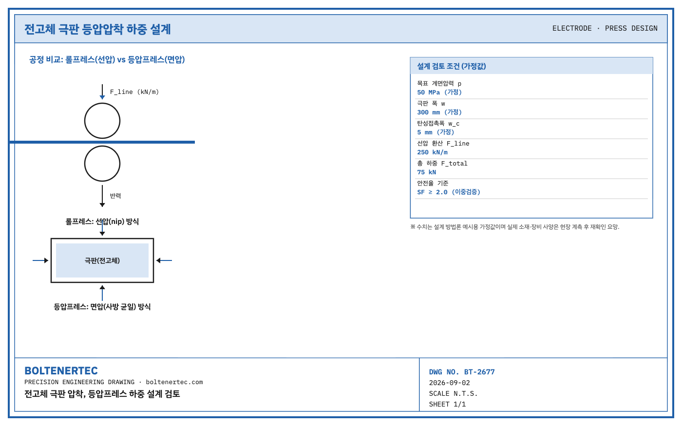
Roll press is a continuous process based on line load, giving high productivity, but it produces localized pressure non-uniformity; isostatic press applies uniform pressure, but as a batch process it breaks R2R continuity — a fundamental conflict. The question of this review is how to integrate the isostatic-compaction process into an existing R2R electrode line.
Kinematic Analysis
Roll press applies line load by passing the electrode through the nip between upper and lower rolls, with the load-transfer path running roll shaft → bearing → frame. If deflection occurs in this path from the roll’s self-weight and reaction force, pressure deviation arises across the electrode width, and at a solid-state interface this translates directly into localized contact defects. Isostatic press applies equal pressure from all directions through a diaphragm or hydraulic medium, changing the load-transfer path to diaphragm → platen → frame. The fundamental difference between the two methods is the pressure-application mechanism, not material properties, so the designer must first define the target contact pressure (MPa) and then convert it into the load for each method.
Calculation / Formula Verification
The following assumed conditions are used for this design review. Actual material and equipment specifications should be confirmed after field measurement. Target interfacial pressure $p = 50\text{ MPa}$ (assumed value; basis: literature on ceramic-based solid-electrolyte compaction reports a range of tens to hundreds of MPa, estimate), electrode width $w = 300\text{ mm}$ (assumed value), elastic contact width between rolls $w_c = 5\text{ mm}$ (assumed value; basis: typical value for steel-roll elastic contact range).
Converted to roll-press line load, this gives the following.
$$F_{line} = p \times w_c = 50\text{ MPa} \times 5\text{ mm} = 250\text{ N/mm} = 250\text{ kN/m}$$
The total load across the full electrode width is as follows.
$$F_{total} = F_{line} \times w = 250\text{ kN/m} \times 0.3\text{ m} = 75\text{ kN}$$
This is a higher pressure range than the typical line-load range for NCM wet-electrode calendering (roughly 50–150 kN/m per industry literature, estimate), which has the practical implication that roll deflection management and crown correction become key to securing the safety factor. The roll shaft’s bending stress and the bearing’s rated load must each be independently calculated to doubly secure a safety factor of 2.0 or above; if either value falls short, a redesign to increase roll diameter or reduce bearing span is required. Actual shaft material and surface hardness should be confirmed after field measurement.
Shop-notes
As an alternative mechanism, a hybrid structure could be considered, placing an offline batch-type isostatic press station downstream of the R2R line and absorbing continuity with a buffer winder. However, the batch approach carries chamber open/close and sealing maintenance burden and takt-time loss, so it was given lower priority as only a compromise rather than a full replacement. Machinability note: the roll surface subject to repeated high-pressure contact should consider tungsten-carbide (WC-Co) coating or nitriding treatment, and straightness tolerance control is the key machining variable governing interfacial pressure uniformity.
Design-Reflection Checklist
- Recalculate the roll line-load conversion against the target contact pressure (MPa)
- Confirm roll deflection amount and crown correction value
- Secure bending-stress and bearing-load safety factors of 2.0 or above independently for the roll shaft
- Finalize roll surface hardness and straightness tolerance specifications (confirm after field measurement)
- Re-size buffer winder capacity when supplementing with a batch approach
One-Line Summary
Solid-state electrode compaction requires reconstructing the load design around contact pressure rather than line load.