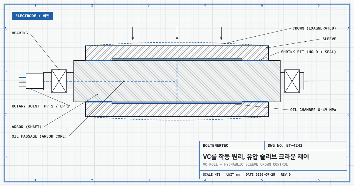
A VC roll (Variable Crown Roll) is a roll that feeds high-pressure oil into a cylindrical oil chamber between the arbor and the sleeve, swells the sleeve centre, and uses that pressure to change the roll crown during operation. The design review starts not at the hydraulic unit but at the shrink fits at both sleeve ends. Those joints carry the rolling load and seal the high-pressure oil at the same time.
1. Problem Definition — A Fixed Crown Fits Only One Line Load
A calender roll deflects at its centre under line load. A ground fixed crown pre-enlarges the centre diameter by that deflection. A fixed crown cancels deflection at one design line load only. When the product changes and the line load changes, the thickness deviation across the width returns.
This is the mechanical contradiction. The roll has one shape, but operation has many conditions. If a mechanism changes the roll shape during operation, where does it send the load, and what sets its limit? The VC roll is the rolling-mill answer to that question.
The operating logic is simple. According to Nippon Steel, if edge waves appear in the rolled material, pressure is increased until the material flattens. If center buckling appears, pressure is decreased.
2. Kinematic Analysis — Load Path Through Sleeve, Oil Chamber and Arbor
Sumitomo Metal Industries developed the VC roll and first applied it in 1977 to a 2-high (2Hi) skin-pass mill for hot-rolled coils. Sumitomo Metal merged with Nippon Steel in 2012 to form Nippon Steel & Sumitomo Metal, which was renamed Nippon Steel Corporation in 2019. The current supplier is Nippon Steel, under the product name VCROLL™. “Nippon Steel VCROLL” is correct for the supplier; the developer was Sumitomo Metal.
The structure reduces to three parts. The sleeve is shrink-fitted over the arbor, and the rotary joint sits at the arbor end. The cylindrical clearance between sleeve and arbor is the oil chamber. High-pressure oil flows through the rotary joint and the central arbor passage into the chamber and swells the sleeve centre. The rotary joint has one high-pressure port and two low-pressure ports for lubrication and cooling.
Following the load path shows the design point. At the sleeve centre, the rolling load passes through the oil layer into the arbor. At the sleeve ends, it passes through the shrink-fit surfaces into the arbor. The arbor sends this load to the bearings at both ends. Meanwhile the crown-control pressure pushes the sleeve bore and the arbor surface in opposite directions. The crown-control force is therefore an internal force closed inside the roll.
| Item | Value | Source |
|---|---|---|
| Developer / first use | Sumitomo Metal Industries, 1977, 2Hi skin-pass mill | Trans. ISIJ 23(10), 1983 |
| Current supplier | Nippon Steel (VCROLL™) | Nippon Steel product page |
| Hydraulic system | Primary circuit held at 20 MPa, booster controls 0–49 MPa | Nippon Steel product page |
| Rotary joint (current diagram) | Max 850 rpm, max operating 49 MPa, resisting 74 MPa, guaranteed 1×10⁸ revolutions | Nippon Steel structure diagram |
| Hydraulic spec (1983) | 0–500 kgf/cm², ramp 100 kgf/cm²/s, accuracy ±5 kgf/cm² | Trans. ISIJ 1983 |
| Sleeve radial expansion | 825×1,950 mm roll up to 0.31 mm / 1,382×2,038 mm roll 0.26 mm (500 kgf/cm²) | Trans. ISIJ 1983 |
| Transfer to material (4-high mill back-up roll) | About 1/2 to 1/5 of the diametral expansion | EP0019737A1 |
| Fatigue safety factor range | 1.5 to 3 | EP0019737A1 |
Another roll shares the name. In paper machines, a “VC-Roll” has a shell rotating on a fixed internal shaft, with hydraulic elements or an oil chamber pressing the shell from inside (OverMade product description). Its load path differs from Sumitomo’s shrink-fitted sleeve on an arbor. The two specifications must not be mixed.
3. Calculation/Formula Verification — Pressure Resolution and Response Time
First, align the units. The 1983 maximum pressure of 500 kgf/cm² converts to MPa as follows.
$$p_{max}=500\times 0.0980665=49.03\ \mathrm{MPa}$$
Here $p_{max}$ is the maximum chamber pressure (MPa). It matches the current 0–49 MPa range. The pressure ceiling in the 1983 paper and in the current product description is the same.
Next, expansion per unit pressure. Divide the 0.26 mm radial expansion of the 1,382×2,038 mm roll by the maximum pressure. Expansion is assumed proportional to pressure (linear assumption).
$$k=\frac{\Delta r_{max}}{p_{max}}=\frac{0.26}{49.03}=0.0053\ \mathrm{mm/MPa}$$
Here $k$ is the radial expansion coefficient (mm/MPa) and $\Delta r_{max}$ is the radial expansion at maximum pressure (mm). Each 1 MPa changes the radius by 0.0053 mm.
Inserting the pressure accuracy of ±5 kgf/cm² (±0.49 MPa) gives the crown resolution.
$$\Delta r_{res}=k\times 0.49=0.0026\ \mathrm{mm}$$
$$\Delta h_{res}=2\,\Delta r_{res}\times\frac{1}{5}=0.0010\ \mathrm{mm},\qquad 2\,\Delta r_{res}\times\frac{1}{2}=0.0026\ \mathrm{mm}$$
$\Delta r_{res}$ is the radial change for the pressure accuracy (mm) and $\Delta h_{res}$ is the change transferred to the material crown (mm). The transfer ratio of 1/2 to 1/5 is the value EP0019737A1 gives for a VC roll used as the back-up roll of a 4-high mill. The back-up roll expansion reaches the material through the work rolls. One pressure-control step appears as 0.0010 to 0.0026 mm in the material. Comparison with electrode thickness tolerance must use the product specification.
$$t_{resp}=\frac{500\ \mathrm{kgf/cm^{2}}}{100\ \mathrm{kgf/cm^{2}/s}}=5\ \mathrm{s}$$
$t_{resp}$ is the time from zero to maximum pressure at the response speed in Table 1 of the 1983 paper (s). The paper’s text gives the response speed as more than 100 kgf/cm²/s, so 5 s is an upper bound. At an assumed line speed of 60 m/min, up to 5 m of material passes while the crown changes (assumed value, recalculate for site conditions). This sets the upper bound of the transition length for a product changeover.
The safety factor is verified on two systems. The first is sleeve fatigue. Sumitomo’s patent (EP0019737A1) states that VC rolls can be designed with a fatigue safety factor of 1.5 to 3. The second is the pressure margin of the rotary joint.
$$SF_{2}=\frac{p_{resist}}{p_{op,max}}=\frac{74}{49}=1.51$$
Here $p_{resist}$ is the rotary-joint resisting pressure (MPa) and $p_{op,max}$ is the maximum operating pressure (MPa). Both systems sit near a lower bound of 1.5. Raising the maximum pressure to widen the crown range eats the rotary-joint margin first.
4. Practical Application (Shop-notes)
- Electrode calenders: this review found no primary source for VC rolls in lithium-ion electrode roll presses. Hitachi Power Solutions states that it adopts a “roll deflection compensation mechanism” that corrects deflection even when the material load or width changes, but does not disclose the mechanism type. Youth Engineering lists a bending mechanism as an accessory of its electrode roll press.
- Alternative mechanism — roll bending: a bending force applied at the roll necks cancels deflection. Reason not adopted here: the bending force enters through the bearing housings, so it must be added to the bearing load calculation. In a VC roll the control force closes inside the roll and adds nothing to the bearing load.
- Rotary joint speed limit: at 850 rpm the roll surface speed is $v=\pi Dn$. For an 825 mm roll this is 2,203 m/min. Before speed, add the low-pressure lubrication and cooling line (0–0.3 MPa) to the utility drawings.
- Machinability: finish the sleeve bore and the arbor diameter at the shrink fits by grinding to control roundness and interference. The central arbor passage requires deep-hole machining along the roll length (passage location per Nippon Steel; machining method estimated). The interference value is not published.
- Changeover: include the transition length during crown change (up to 5 m at the assumed speed) in the scrap length of the changeover procedure.
5. Design Checklist
- Is the required crown change calculated over the full line-load range (minimum to maximum)?
- Is the transfer ratio (1/2 to 1/5 for a multi-high mill) measured on the electrode roll press?
- Is the thickness change for ±0.49 MPa pressure accuracy within product tolerance?
- Does maximum-pressure operation keep the rotary-joint margin of 1.51?
- Is the rotary-joint low-pressure lubrication and cooling line on the utility drawings?
- Are the grinding tolerance and seal test method for the shrink fits specified on the drawing?
Items Requiring Confirmation
- Shrink-fit interference: no value in public sources.
- Use in lithium-ion electrode roll presses: no primary source found.
- Rotary joint specification gap: the 1983 paper gives 500 rpm and 1×10⁷ revolutions, the current diagram 850 rpm and 1×10⁸. Confirm current values with the supplier.
- Transfer ratio 1/2 to 1/5: 4-high mill back-up roll basis. Values for a 2-high electrode roll press and electrode material are unconfirmed.
- Linear assumption: proportionality between pressure and expansion is an assumption of this article.
One-line summary: A VC roll closes the crown-control force inside the roll through an internal oil chamber, and its limit is set not by the hydraulic unit but by the rotary-joint pressure margin and the sleeve shrink fits.
Sources: Nippon Steel VCROLL™ product page · Nippon Steel company history · T. Masui et al., Trans. ISIJ 23(10) 846-853, 1983 · Bulletin of the Japan Institute of Metals 17(6) 542-543, 1978 · EP0019737A1 (Sumitomo Metal Industries, priority 1979-05-24) · OverMade VC-Roll product description · Hitachi Power Solutions roll press · Youth Engineering roll press