Battery equipment mechanical design is the job of deciding, in dimensions and tolerances, the frame and moving parts of the machines that press, slit and wind electrode strip, and putting those decisions on drawings.
- A mechanical design engineer sets a machine’s shape, the loads it must carry and the error each part may have, all as numbers on a drawing. My team runs design, build and the factory acceptance test (FAT)1 as one 8-month cycle.
- Of all the numbers on a drawing, tolerance2 takes the longest to learn. For diameters from 30 to 50 mm, ISO 286-1 gives IT6 a width of 16 µm. IT11 is 160 µm, ten times wider.
- Every part can pass inspection and the assembly can still be off. Stack three IT7 parts in one direction and the worst case opens up to 75 µm.
When a new equipment drawing lands on my desk, I read the small ± signs next to the dimensions before I look at the shapes. The 3D model shows the shape. Only those signs say how many microns that shape is allowed to drift. Whether a machine will be out of line after assembly is mostly settled at the moment those signs are chosen.
Boltenertec, from roll press and slitter design work
I have been designing battery roll-to-roll (R2R)3 equipment since 2005. Most of my work has been on the roll press4, which squeezes electrode strip to a set thickness, and the slitter, which cuts a wide electrode into narrower lanes. I have also designed the Variable Crown Roll5 and high-temperature coating rolls. All four exist to move a thin strip through a fixed position under a fixed force.
The mechanical designer picks the numbers: how much load the machine has to take and how accurate every part has to be. Those numbers travel as drawings to the machine shop and the assembly floor. The shop builds exactly what the drawing says. A wrong drawing produces a wrong machine, which is why I measure my work against zero engineering change orders (ECO)6.
From one drawing to a working machine
My team works in 8-month laps. A lap starts with design, runs through part machining and assembly, and ends with the acceptance test held at the build site before the machine ships to the customer. The design team sits at two locations, and we keep schedules and drawing history together in Notion. Because the lap is long, a small design slip often stays hidden until assembly, months later.
The 3D printer I run as a hobby is a handy comparison. You model a part on the computer, print it, then push it into its mating part to see whether it fits. Equipment design follows the same order. Modeling is design, printing is machining and assembly, and the fit check is the FAT.
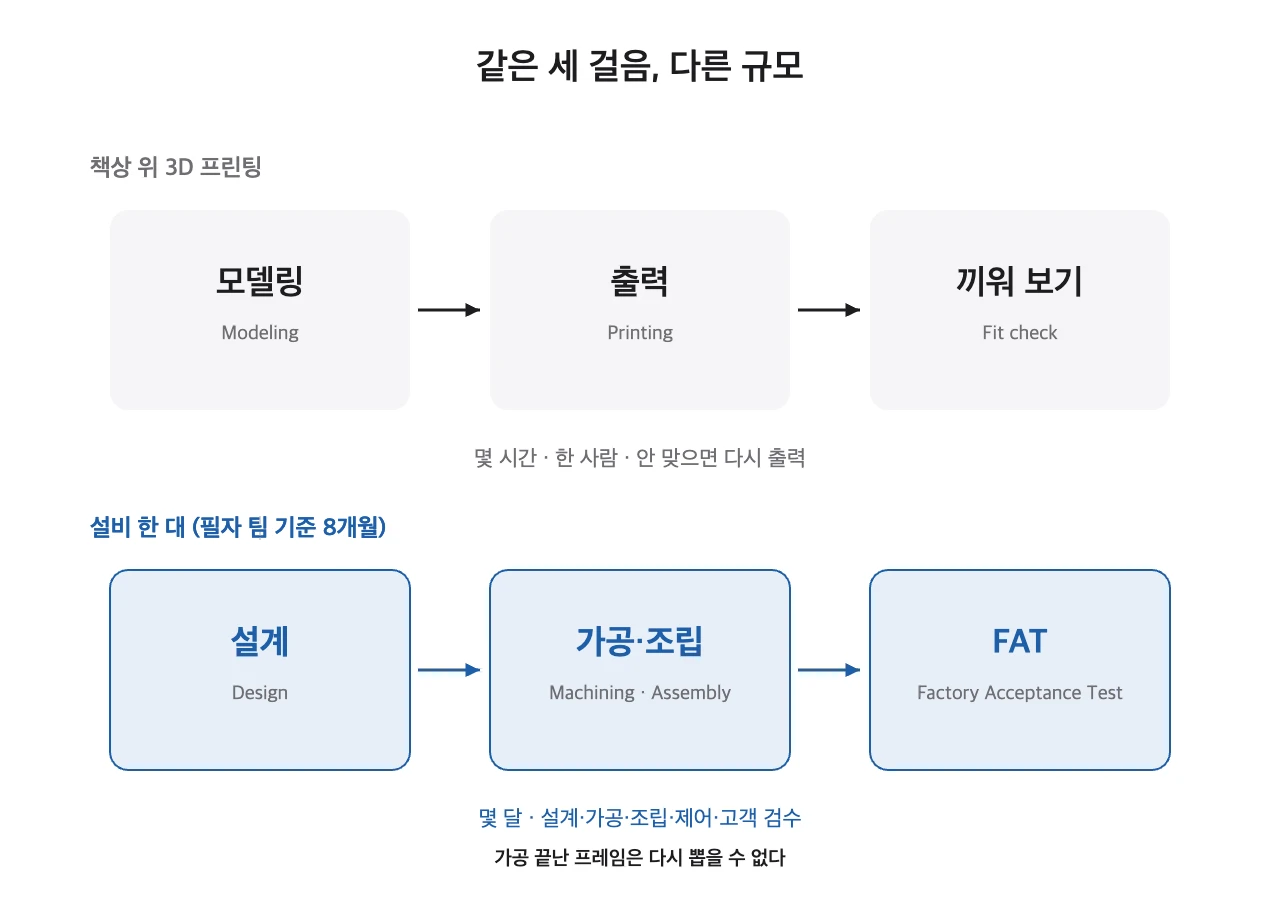
Where the comparison breaks down is scale. A printer lets one person finish all three steps at one desk in a few hours. With equipment, the designer, the machine shop, the assemblers, the controls engineer and the customer’s inspector each own a step. A bad print can simply be printed again. A machined frame cannot.
The name FAT comes from process automation, where IEC 62381 lays out the test. That standard is written for automation systems, but equipment makers use the same name for the pre-shipment test the customer witnesses. Only a machine that passes FAT leaves for the customer’s plant, and once installed it goes through a site acceptance test (SAT)7.
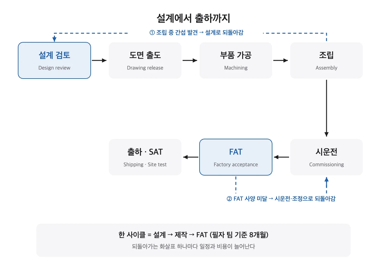
The arrows run backward in two places. If parts collide during assembly, the work goes back to design. If the machine misses spec at FAT, it goes back to commissioning and adjustment. Every backward arrow adds time and cost, so I read the tolerance callouts one more time right before a drawing is released.
The equipment a mechanical designer handles is spread across the whole plant. Using the boxes from the value chain post in this series, equipment makers sit between materials and cells. My own corner is the electrode line: coating, pressing, slitting and winding.
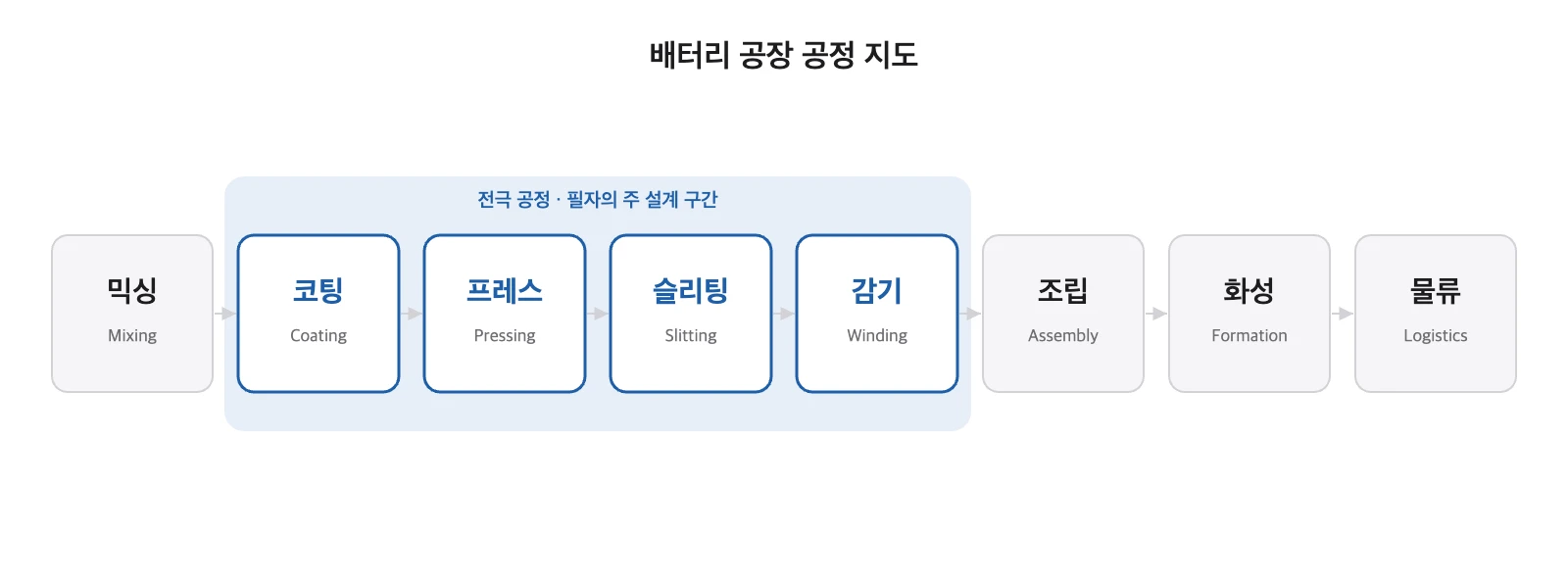
Change the process and the numbers you care about change too. Electrode equipment handles long rolls and thin strip at the same time. A roll that bends even slightly makes the strip thickness vary across its width, and, as the winder post showed, a single roll diameter can reshape the whole torque calculation. In cell assembly equipment, the main design targets shift to grippers that pick up single sheets and to how those sheets are located.
What separates 16 µm from 160 µm?
Every dimension on a drawing carries an allowed range. Bore a 40 mm hole and the real diameter will never come out at exactly 40.000 mm, so the drawing states in advance how far off still counts as a pass. ISO 286-1 sorts the size of that range into steps called IT grades8 and lists them in a table.
On the drawing itself, the rule shrinks to a short code. A hole marked Ø40 H7 passes if its diameter lies between 40.000 mm and 40.025 mm. The H puts the lower limit on the nominal size, and the 7 points to the IT7 width of 25 µm. It looks like a cipher to a newcomer, yet a machinist picks the cutting tool and the gauge from that code alone.
Both values belong to the same size range, and they differ by exactly a factor of ten. Follow the table and you find that every five grades the width grows tenfold.
Which grade to use depends on what the surface mates with. A shaft seat that takes a bearing needs a tight grade. A hole that only has to let a bolt through gets a loose one. Tighter grades add machining steps and make measurement harder. A drawing with every surface on a tight grade looks thorough, but to me it reads as a drawing that never decided what matters.
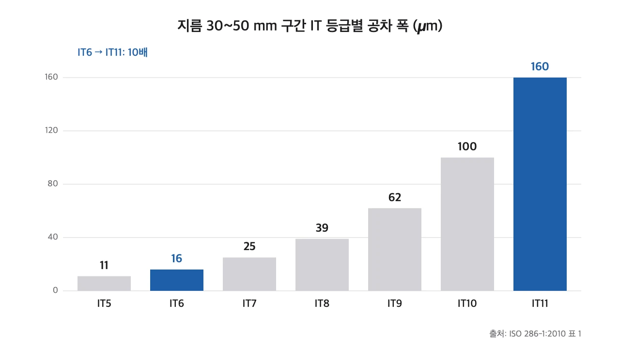
The bars climb like a staircase. Moving one grade is a choice between multiples, not a fine trim. Even neighbors IT7 and IT8 sit at 25 µm and 39 µm, more than 1.5 times apart. Before I move a surface by one grade, I check the part it mates with.
If every part meets its drawing tolerance, the assembled machine will match the drawing.
Tolerances add up. Stack three IT7 (25 µm) parts in one direction and the worst-case total reaches 75 µm (own calculation).
This is called tolerance stack-up9. It explains why parts that each passed inspection can leave a gap or refuse to fit once assembled. The designer’s task is less about tightening every tolerance and more about shortening the chain they add up along. Dimension several features from a single datum10 and the number of linked dimensions drops first.
My own design rule grows from the same place. I hold that equipment performance and service life are decided by assembly tolerance control and by the stiffness of the load path, more than by simulation plots. A simulation assumes the shape matches the drawing exactly. The real machine runs offset by its tolerances.
What should a newcomer learn first?
CAD is the program that stays open longest in my day. I use AutoCAD for 2D manufacturing drawings and Autodesk Inventor for 3D models and assembly checks. Repetitive drafting gets cut down with AutoLISP11 scripts. Calculations such as roll deflection or bearing life I cross-check with calculation tools I wrote in Python.
| Tool | What I use it for | Where to start |
|---|---|---|
| AutoCAD | 2D manufacturing drawings, dimensions and tolerances | KS B 0001 mechanical drawing rules |
| Autodesk Inventor | 3D part and assembly models, interference checks | Assembly constraints and interference checks |
| MechClick | Design aid I use alongside AutoCAD | Learn it together with your company’s drawing template |
| AutoLISP | Automating and debugging repetitive drafting | Write one small command yourself |
| Python (PySide6, Tkinter) | Engineering calculation tools | Turn a hand calculation into a function |
| IEC 61131-3 Structured Text | PLC12 logic, checking the boundary with controls | Read input and output signal names |
The bottom two rows are not core mechanical design. I build calculation tools and read PLC logic to get the boundary right. Knowing how far the machine moves, and what each sensor reads and where, lets me talk with the controls engineer in the same terms. The details of control implementation need a separate review and stay outside this post.
If you are preparing for this job, I would train your eye for reading drawings before your CAD speed. I placed in the mechanical design/CAD category of a skills competition. In a competition, drawing lines accurately and fast earns points. In front of an equipment drawing, what holds me longest is the reasoning behind each tolerance. Opening a tolerance table and guessing which grade the holes and shafts around your home might be costs nothing.
Every machine in the plant exists first as numbers on a drawing, from the frame down to a single bolt hole. Guards between rolls where a hand could be caught are no exception. Korea’s Occupational Safety and Health Standards Rules on caught-in hazards fix where those guards go, and that happens at the drawing stage.
One step further, for engineers
Stack-up is calculated two ways. The worst-case method assumes every part sits at the same end of its range at once.
$$T_{wc}=\sum_{i=1}^{n}T_i$$
The statistical method (RSS) assumes part deviations are independent and close to normally distributed.
$$T_{rss}=\sqrt{\sum_{i=1}^{n}T_i^{2}}$$
$T_i$ is the tolerance width of part i (mm) and $n$ is the number of parts stacked in one direction. With three IT7 parts in the 30–50 mm range, $T_i=0.025$ mm gives $T_{wc}=0.075$ mm and $T_{rss}=0.043$ mm (own calculation, assumed values).
Features that must stay coaxial, such as bearing housings, I check by worst case. RSS is a basis only for high-volume parts from a stable process. Equipment parts are often one-offs or small batches, so the statistical assumption may not hold; confirm with field measurement.
Machinability note: to cut the number of stacked parts, assign a datum on the drawing so the reference face and the bearing seats are machined in one setup. The alternative mechanism is setting the gap with adjustment shims. Results vary by assembler and the adjustment history is lost on reassembly, so I do not adopt it as the baseline.
Related posts: pallet locating pin tolerance design, how a VC roll works, calendering roll deflection check
- Mechanical design sets a machine’s shape, the loads it carries and each part’s allowed error as numbers on a drawing.
- My team repeats design, build and FAT as one 8-month cycle.
- For 30–50 mm, IT6 is 16 µm and IT11 is 160 µm. Every five grades the width changes tenfold.
- Even passing parts stack their tolerances. Shortening that chain is the designer’s job.
- Start by reading drawings and tolerance tables, not by chasing CAD speed.
Glossary
- FAT (Factory Acceptance Test): a test at the build site, with the customer, to confirm the machine works to spec before it ships. ↩
- Tolerance: the range a dimension may stray from its target and still pass. The narrower the range, the more precisely the part must be made. ↩
- Roll-to-roll (R2R): a production method that unwinds a long strip from a roll, processes it, and winds it up again. ↩
- Roll press: a machine that passes electrode strip between an upper and a lower roll to press it to a set thickness. ↩
- Variable Crown Roll: a roll whose outer profile can be changed to offset the bending at its middle under load. ↩
- ECO (Engineering Change Order): revising and reissuing a drawing that has already been released. Once machining or assembly has started, it adds time and cost. ↩
- SAT (Site Acceptance Test): a second check run after the machine is installed at the customer’s plant. ↩
- IT grade: a step of tolerance width that ISO 286-1 sets for each size range. A smaller number means a narrower width. ↩
- Tolerance stack-up: the growth of total error when parts are stacked in an assembly and each part’s error adds to the next. ↩
- Datum: the face or axis a drawing uses as the starting point for measuring other dimensions. ↩
- AutoLISP: a scripting language inside AutoCAD that bundles repetitive tasks into a single command. ↩
- PLC (Programmable Logic Controller): an industrial controller that runs a machine’s motors and sensors in a set sequence. ↩
Sources
- ISO 286-1:2010, Geometrical product specifications (GPS) — ISO code system for tolerances on linear sizes — Part 1, Table 1 (IT5–IT11 values for 30–50 mm). Equivalent: KS B ISO 286-1. Values cross-checked against Wikipedia, “IT Grade”, https://en.wikipedia.org/wiki/IT_Grade
- IEC 62381:2024, Automation systems in the process industry — Factory acceptance test (FAT), site acceptance test (SAT), and site integration test (SIT), https://webstore.iec.ch/en/publication/67572
- ISO 286-2:2010, Part 2: Tables of standard tolerance classes and limit deviations for holes and shafts (H7 hole, 30–50 mm: upper deviation +25 µm, lower 0). Equivalent: KS B ISO 286-2.
- KS B 0001, Mechanical drawing.
- Own calculation. Stack-up: three IT7 (25 µm) parts, worst case 75 µm, RSS 43 µm (assumed values).
- Author’s work history. 8-month design-build-FAT cycle and tool list.
This post is meant to help readers understand industry and technology. It is not a recommendation to buy or sell any stock.