A roll press1 is the electrode-line machine that squeezes a freshly coated electrode between an upper and a lower roll to set its thickness and density. The squeezing step itself is called calendering2.
- A roll press closes up the gaps between particles in the dried electrode layer. Commercial electrodes are pressed to a porosity3 of roughly 30%.
- A pressed electrode gets thinner and also longer. In one set of measurements, stretch along the running direction was up to four times the stretch across the width.
- The bare foil at the edges stretches less, so it wrinkles. If the roll bows in the middle, thickness across the width drifts too. I treat both as one problem of roll and frame stiffness.
Most people picture pressing as pure thinning. Anyone who has rolled out dough knows better: the dough also creeps forward and back. An electrode does the same thing, with one difference. It can barely spread sideways, so nearly all of the extra length goes into the running direction.
A roll press only makes the electrode thinner.
Whatever thickness it loses, the electrode gains as length. Researchers at KIT in Germany measured running-direction stretch of up to four times the cross-direction stretch.
The trouble shows up at the edges. Both sides of the electrode web carry a strip of foil with no coating on it, which the industry calls the uncoated area4. While the coated middle is squeezed and grows longer, the uncoated strip hardly gets touched. Long middle, short edges: the foil along the boundary has nowhere to go but into ripples.
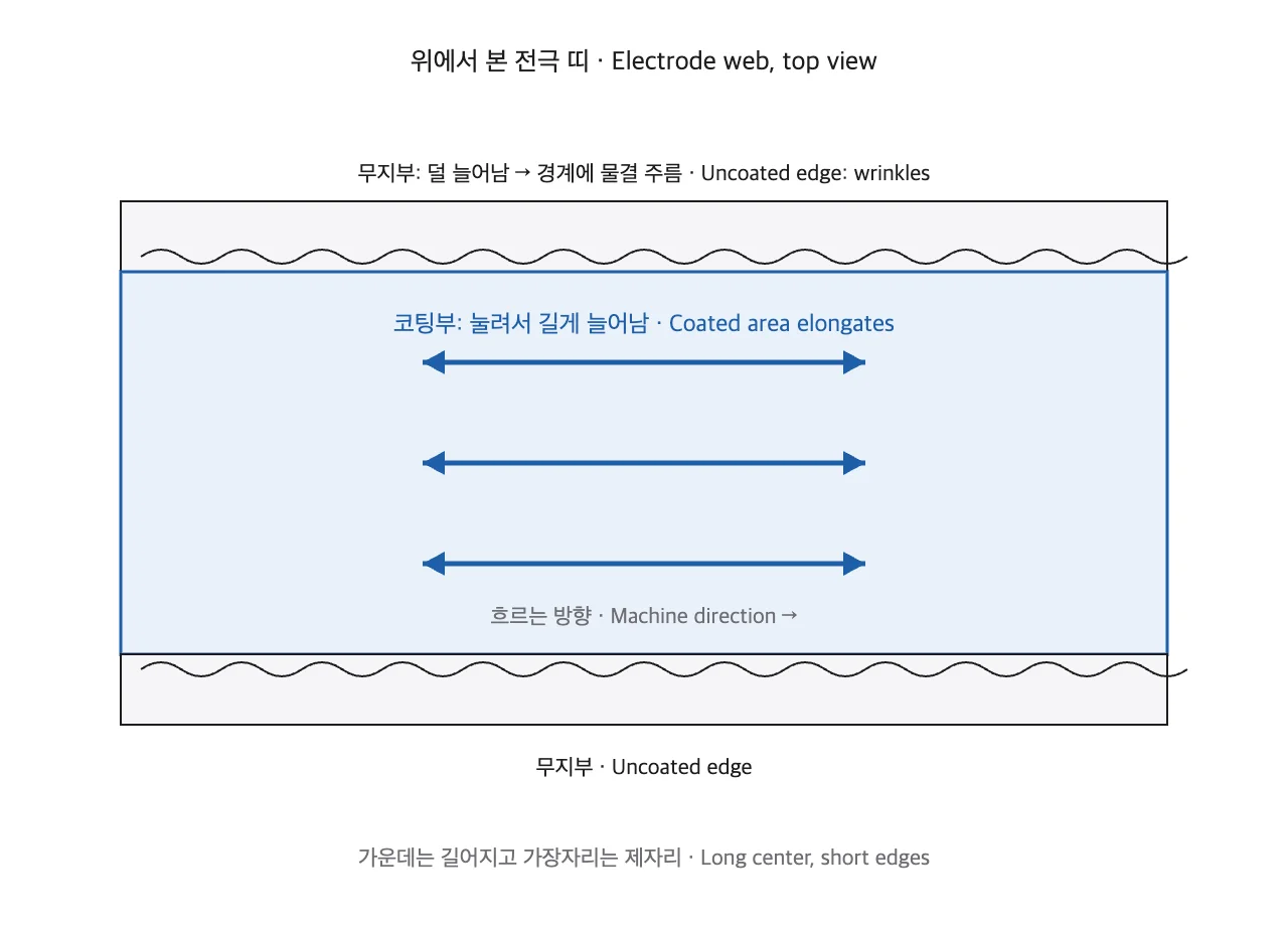
The same paper describes the whole web curving sideways like a blade as the coating stretches, and the authors call it the saber effect. A curved web no longer lines up with the knives at the next step, slitting5. That is why I add a separate line for length change whenever I review a roll press specification.
What happens in the gap between two rolls
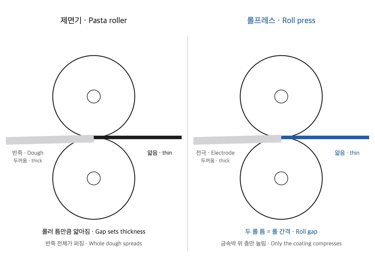
The kitchen tool closest to a roll press is not a rolling pin but a pasta machine. Turn the crank and two facing rollers grab the dough, which comes out as thin as the gap. Close the gap one notch, feed it again, and the sheet gets thinner and longer.
The dough is the electrode, the two rollers are the upper and lower rolls, and the space between them is the roll gap.
Pasta dough moves as one piece, while the electrode powder layer is stuck to a thin metal foil. It cannot spread evenly the way dough does, which is where the wrinkles come from. The pace differs as well: even a research roll press feeds electrode continuously at up to 30 m/min.
In industry terms, the bottom of a freshly coated electrode is the current collector6, a metal foil. On top of it sits a dried layer of active material7 powder full of voids. The roll press compresses that layer down to a target porosity, and particle contact and adhesion to the foil rise along the way.
The force the rolls apply is rarely quoted as a total. It is quoted per millimetre of electrode width, in N/mm, and called the line load8. The same total force spread over a wider web gives a lower line load. When I open a datasheet, the line load row is the first one I look for.
A real machine has more than two rolls. An unwinder feeds the coated web in, a rewinder takes it away, and a hydraulic cylinder above the rolls pushes them together. That force travels back through the bearing housings into the frame.
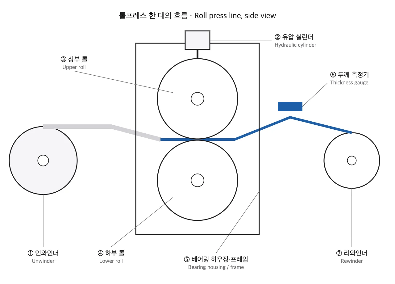
Once the electrode leaves the nip, the compressed layer recovers slightly. This elastic recovery is called spring-back9. So the roll gap is set tighter than the target thickness, and the thickness gauge sits after the rolls.
How hard, and how dense
The research roll press at KIT uses rolls 700 mm in diameter and 500 mm wide. The diameter is larger than the width. Keep that ratio in mind; it makes the roll-bending part easier to follow.
A line load of 2,000 N/mm is like placing about 204 kg on every millimetre of width. Across the full 500 mm that comes to 1,000 kN, or about 102 t between the rolls (own conversion, 1 kgf = 9.81 N).
How much an electrode has been squeezed is expressed as the compaction rate, the percentage of its original thickness that was removed. The same team pressed a cathode and an anode lightly and heavily and compared the results.
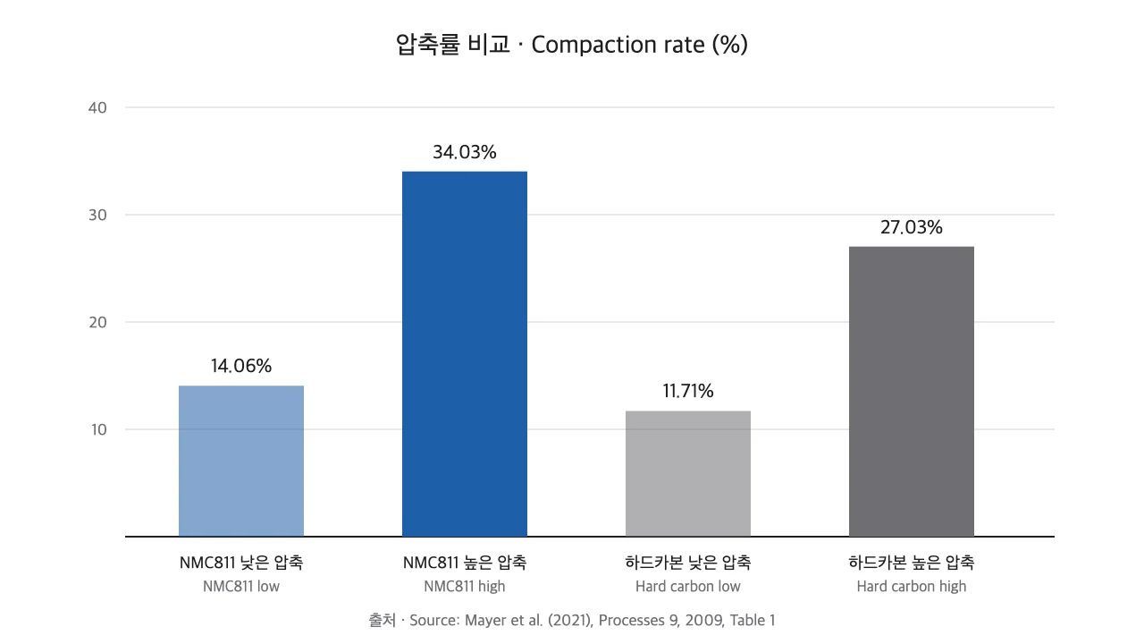
The cathode density the researchers judged optimal, 2.55 g/cm³, matched a compaction rate of 14.06%. Pressing harder, up to 34.03%, did not do better. The paper also notes that wrinkle amplitude grew with compaction. So before I raise the line load, I work on its variation across the width.
| Setting chosen by the designer | What it changes | Limits reported in the literature |
|---|---|---|
| Line load | Porosity, density, wrinkle size | Above 1,960 N/mm, strong deformation of the carbon-binder domain has been reported (Chen et al., Sec. 2.3) |
| Roll temperature | Electrode conductivity | Conductivity is reported to depend mainly on calendering temperature (Chen et al., Sec. 2.2). The KIT machine heats its rolls up to 90 °C |
| Roll diameter and face length | Roll bending, thickness spread across the width | No published figure. See my own calculation in the field note below |
| Roll gap | Final thickness | Spring-back means gap and final thickness are not equal |
Only the third row has an empty cell. Process papers rarely deal with the link between roll diameter and roll length. It is a calculation for the mechanical design side.
Where I look first on a roll press drawing
I have designed R2R equipment such as roll presses and slitters since 2005. On a roll press drawing, I check the ratio of roll diameter to bearing span before I look at surface finish. A roll is a thick steel bar carried by bearings at both ends. Press on the middle and it bows, however slightly.
In the beam formula from strength of materials, bending deflection scales with the fourth power of the span and inversely with the fourth power of the diameter. Keep the diameter and line load fixed, double the bearing span, and bending deflection rises sixteenfold.
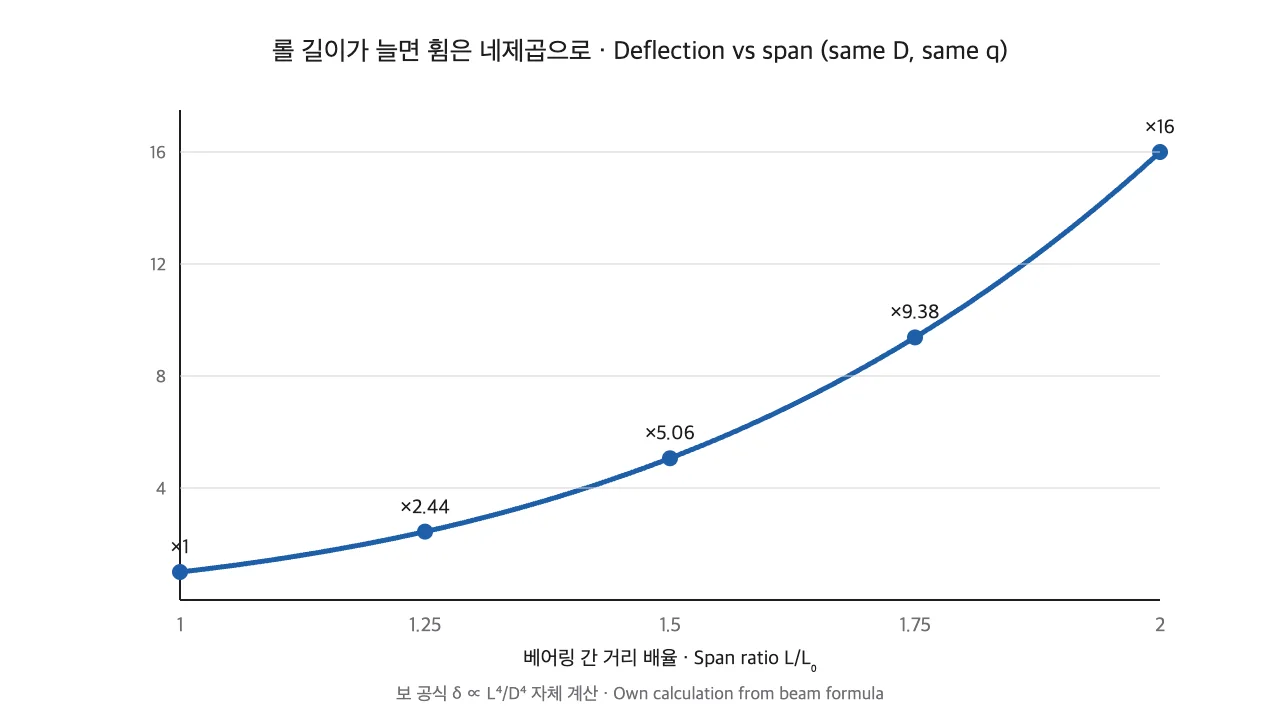
A bowed roll opens the gap in the middle, so the centre of the electrode is pressed less than its edges. Thickness then varies across the width, and the stretch mismatch from earlier grows with it. I ran the KIT numbers. Even a 700 mm roll sags about 2.5 μm at mid-span under a line load of 1,000 N/mm (own calculation, estimate). For an electrode whose thickness is controlled in micrometres, that belongs on the measurement list.
The Variable Crown Roll10 I have designed pre-swells the middle of the roll by the amount it will bend. Internal pressure bulges the shell so the gap runs flat once the load is on. A steel bar never bends zero. My order of work is to calculate the deflection first, then return that amount through the crown.
The machine’s place in the line is tied to the same judgement. Upstream sits coating and drying11; downstream sits the slitter.
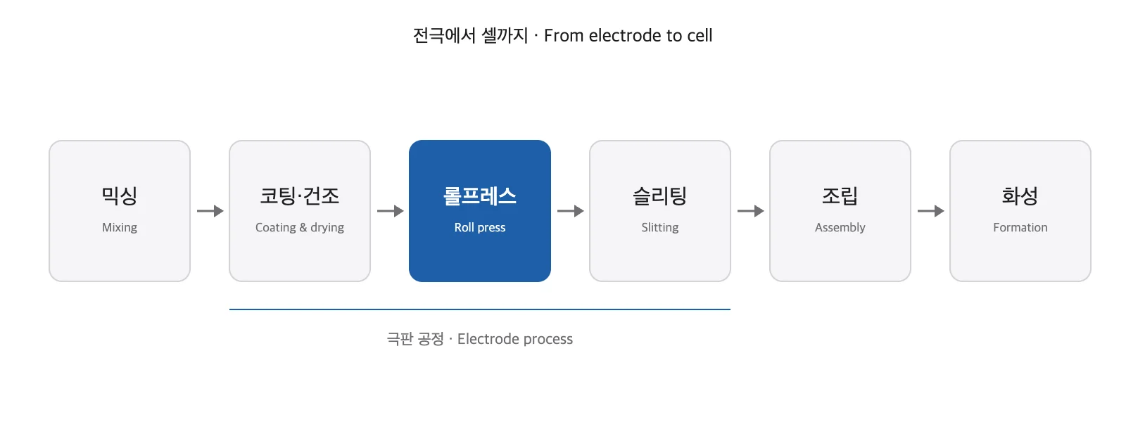
If the coating upstream is uneven, the roll press inherits that spread. Whatever bending and wrinkling the roll press adds is handed on to the slitter. Slurry making is covered in the mixing article, and the step where cut electrodes become cells in the notching and stacking article.
For a mechanical engineering graduate looking for work, this machine is a place where first-year courses get used directly. Roll bending is beam deflection from strength of materials, and bearings and shafts are a chapter of machine element design. I run deflection checks like the one below in a Python calculation tool and carry the results into Autodesk Inventor drawings.
In battery performance terms, electrodes made from the same material still diverge depending on how hard they were pressed. In the KIT study, cells with different compaction differed in capacity retention by up to 5% at 1C. At 2C and 3C the gap widened to 25–30%.
One step further, for engineers
Treat the roll as a simply supported solid round beam. Under an equivalent distributed load, mid-span bending deflection is:
$$\delta_b=\frac{5\,w\,L^{4}}{6\,\pi\,E\,D^{4}}$$
$\delta_b$ is bending deflection (mm), $w$ the equivalent distributed load spread over the bearing span (N/mm), $L$ the bearing span (mm), $E$ Young’s modulus (MPa) and $D$ the roll diameter (mm). Spreading 1,000 N/mm × 500 mm face over $L=700$ mm (assumed) gives $w\approx714$ N/mm. With $E=210{,}000$ MPa (generic steel, assumed) and $D=700$ mm, $\delta_b\approx0.9$ μm. In a short, thick roll, shear deflection exceeds bending deflection; with a shear coefficient of 0.9 it adds about 1.6 μm, for a total of about 2.5 μm (own calculation, estimate). Bearing, housing and frame deformation and roll surface contact are left out, so the real gap change is larger. Confirm by measurement on site.
Strength gets two separate checks. Peak bending stress under the same load is about 1.3 MPa. Against a 345 MPa yield steel (assumed), the static safety factor is about 265. Because the roll sees one full bending reversal per turn, fatigue is checked as well. Against a 300 MPa endurance limit (assumed as half of a 600 MPa tensile strength), the factor is about 230. Both margins are large, so at this size stiffness, not strength, sets the dimensions. Confirm material values against the mill certificate.
Machinability note: roll body cylindricity and crown profile are finished by grinding. A fixed ground crown is simple to machine but goes out of step whenever the line load changes. An alternative mechanism is roll bending, which applies opposing moments at the shaft ends. It needs extra cylinders and extended journals, which enlarge the housing and raise bearing loads, so it is not the baseline here.
Related in-depth articles: VC roll mechanism and hydraulic sleeve crown control, Dry electrode calendering: nip pressure and speed differential, Winder roll torque
When you look at a roll press photo or datasheet, check these four boxes first.
- Is the line load stated in N/mm rather than as a total force
- Are roll diameter, bearing span and the crown method for countering bending given
- Is there a stated measure against wrinkling of the uncoated area
- Does a thickness gauge after the rolls measure thickness after spring-back
If any one of the four is missing a number or a method, I ask about it the moment the datasheet arrives.
Glossary
- Roll press: a machine that passes an electrode between an upper and a lower roll to set thickness and density. Also called a calender. ↩
- Calendering: the process of pressing material between rolls to make it thinner and denser. ↩
- Porosity: the share of an electrode layer’s volume that is empty space. Electrolyte soaks into these voids. ↩
- Uncoated area: the strip of bare foil left along the edge of the electrode web. In the finished cell it carries current out. ↩
- Slitting: cutting a wide electrode web lengthwise with knives into several strips of a set width. ↩
- Current collector: the thin metal foil that carries the electrode layer and collects current. ↩
- Active material: the powder in the electrode that actually stores and releases charge. ↩
- Line load: the total roll force divided by the pressed width, in N/mm. ↩
- Spring-back: partial return of a material toward its original thickness after the pressing force is removed. ↩
- Variable Crown Roll: a roll whose crown, the bulge of its body, can be changed by internal pressure. Often shortened to VC roll. ↩
- Coating and drying: spreading electrode slurry thinly on foil and drying it with heat. ↩
Sources
- Mayer, D., Wurba, A.-K., Bold, B., Bernecker, J., Smith, A., Fleischer, J. (2021). Investigation of the Mechanical Behavior of Electrodes after Calendering and Its Influence on Singulation and Cell Performance. Processes, 9(11), 2009. Sec. 1 (porosity, uncoated-edge wrinkles, saber effect), Sec. 2 (roll diameter and width, maximum line load, maximum speed, roll temperature), Table 1 (compaction rates), Sec. 3.1 (optimal density, capacity retention), Sec. 3.2–3.3 (directional elongation, wrinkle amplitude). https://doi.org/10.3390/pr9112009
- Chen, J., Asachi, M., Hassanpour, A., Babaie, M., Jabbari, M. (2025). Modelling of lithium-ion battery electrode calendering: A critical review. Journal of Energy Storage, 123, 116702. Sec. 1 (purpose of calendering), Sec. 2.1 (line load, elastic recovery), Sec. 2.2 (commercial porosity about 0.3, temperature and conductivity), Sec. 2.3 (deformation above 1,960 N/mm). https://doi.org/10.1016/j.est.2025.116702
- The curve in Figure 5, the weight conversion and the 2.5 μm deflection in the text, and the deflection, stress and safety factors in the engineer box are my own calculations using the machine values above, standard beam formulas and stated assumptions.
This post is meant to help readers understand industry and technology. It is not a recommendation to buy or sell any stock.