Dual clamping-pressure design for tab welding jigs is a mechanical prerequisite that must be resolved when a single assembly line handles different battery pack specifications simultaneously.
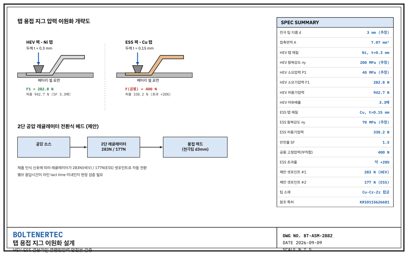
Problem Definition: The Mechanical Contradiction of a Shared Line
Sebang Lithium Battery has separately won orders on the scale of trillions of won for Hyundai Motor’s hybrid (HEV) new-model battery packs and LG Energy Solution’s new ESS battery packs (exclusive report by Korea Economic Daily, September 7, 2026). In both cases, Sebang Lithium Battery does not manufacture the cells itself but handles module and pack assembly.
HEV packs and ESS packs operate in different environments. HEV packs experience large vehicle vibration and shock loads and have fewer cells. ESS packs are dominated by static loads, have more cells, and tend to use wider, thinner connecting tabs to reduce resistance under high current. When the two products differ in tab thickness and shape, a single fixed clamping pressure cannot be used for the resistance-welding jig.
Building two separate jigs per product increases equipment investment cost. Using a single shared jig causes weld non-fusion for the product requiring lower pressure and tab deformation for the product requiring higher pressure. There is one question: what mechanical element is needed to dualize clamping pressure on a single jig base?
Kinematic Analysis: Tab Bend Structure and Pressure Requirements
The basic bend structure of the connecting tab can be referenced in Claims 10 and 11 of Samsung SDI’s registered patent KR101156266B1 (family US8609275B2). It is a three-stage structure consisting of a flat section corresponding to the weld area, an upward-bent inclined section, and a second flat section where the wiring connects. This structure is common across product lines, but the flat-section thickness and width differ by product.
HEV packs tend to use thicker nickel tabs (around 0.3 mm thick) for vibration durability, while ESS packs tend to use thinner, wider copper tabs (around 0.15 mm thick) to reduce resistance loss (an estimate based on general design trends; Sebang Lithium Battery’s actual specifications are undisclosed, so on-site measurement and reconfirmation is required).
Calculation Verification: Clamping Pressure Window and Dual Safety-Factor Check
In resistance welding, electrode pressure P is determined by the applied force F over the contact area A.
$$P = \frac{F}{A}$$
With an electrode tip contact diameter of d = 3 mm (estimated, following common spot-welding tip specifications), the contact area is as follows.
$$A = \pi \left(\frac{d}{2}\right)^2 = \pi \times 1.5^2 = 7.07\ \mathrm{mm}^2$$
For the HEV nickel tab (yield strength σy ≈ 200 MPa, estimated), based on a minimum welding pressure of 40 MPa (estimated, typical range for nickel resistance welding 30–60 MPa), the required applied force is as follows.
$$F_{1} = 40\ \text{MPa} \times 7.07\ \mathrm{mm}^2 = 282.8\ \text{N}$$
Applying a safety factor of 1.5, the allowable pressure and allowable applied force against tab deformation are as follows.
$$P_{allow} = \frac{\sigma_y}{SF} = \frac{200}{1.5} = 133.3\ \text{MPa}, \quad F_{allow} = 133.3 \times 7.07 = 942.7\ \text{N}$$
Since the allowable applied force is 3.3 times the required applied force, the safety factor is sufficient for the HEV tab alone. The problem is the ESS copper tab. Taking the yield strength of annealed copper as 70 MPa (estimated), the allowable applied force at the same contact area is only 330.2 N.
$$F_{allow,Cu} = \frac{70}{1.5} \times 7.07 = 330.2\ \text{N}$$
Using a fixed-pressure jig at 400 N, the midpoint between the two products, is safe for the HEV tab but exceeds the allowable value by 20% for the ESS tab, leaving a risk of tab deformation. This means a single fixed-pressure jig cannot safely cover both products simultaneously.
Shop-notes
- Adopted: A two-stage pneumatic-regulator switching head. Switch between two pressure set points (e.g., around 283 N and 177 N) when the product changes over. It must be confirmed that valve response time is sufficiently short relative to the line’s tact time.
- Alternative (not adopted): A servo-motor continuously variable pressure head. This allows continuous, precise pressure control, but was not adopted because its higher initial investment cost compared to pneumatics was judged to be over-engineering relative to the capacity expansion pace expected at the initial stage of trillion-won-scale order volume.
- Machinability note: The 3 mm electrode tip contact-face diameter is achieved by turning Cu-Cr-Zr alloy stock followed by age-hardening heat treatment. As the contact diameter increases with tip wear, pressure decreases accordingly, so the re-grinding cycle must be managed separately.
Design Reflection Checklist
- ☐ Confirm the two pressure set points by tab thickness/material after on-site measurement
- ☐ Manage electrode tip contact-area tolerance within ±0.05 mm
- ☐ Re-verify safety factor ≥ 1.5 for both set points
- ☐ Confirm jig switchover time fits within the line’s tact time
One-line summary: A tab welding jig on a shared assembly line cannot cover two products with a single fixed pressure value; dualizing pressure set points by product and re-verifying safety factor must come first.