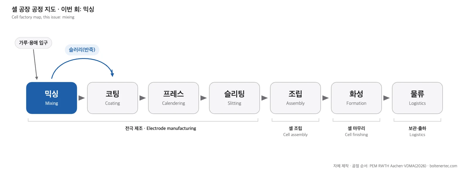
Mixing is the step that turns electrode powders and a liquid into the paste that gets coated onto a battery electrode. It is the first box on the cell factory map, the place where powders delivered to the plant first change form.
- Mixing blends electrode powders with a liquid using rotating blades, then pulls the air out under vacuum. The result is a paste called slurry1, which goes straight on to coating.
- In a sample cathode recipe, the powder is 95% active material, 1% carbon and 4% binder2 (PEM/VDMA). Out of 100 g of powder, only 1 g is carbon.
- Mixing takes anywhere from 20 minutes to 6 hours (PEM/VDMA). Longer and harder does not mean better; one study found electrode performance peaked inside a specific range of mixing intensity (Weber et al. 2024).
- For a 10 GWh plant, mixing equipment costs €30–55 million (PEM/VDMA). By my count, that is about 11% of the equipment budget across 13 process steps.
Why is the slurry made first?
In the previous issue I drew the cell factory as a map of seven boxes, from mixing to logistics. From this issue on, I’ll zoom in on each box in turn, beginning with the first. Mixing comes first because of what an electrode is: a thin metal foil coated with paste and dried. Nothing can be coated until the paste exists.
There is a second reason, and it has to do with contamination. The main reference for this series is a process guide published jointly by the PEM institute at RWTH Aachen University and the German engineering association VDMA. It says foreign particles that end up in the coating cannot be removed later, not even by suction cleaning. Whatever gets into the slurry stays in the electrode.
Even the building is different. In the PEM/VDMA factory concept, slurry production sits in a multi-story building laid out for weighing powders and solvents into the mixers and controlling the process. The coating and drying area, by contrast, is a single-story hall with a high ceiling.
The paste has four main ingredients. Active material3, which stores the energy, makes up most of it. Conductive additive4, which gives electrons a path, is the smallest share. A binder holds the particles together, and a solvent turns everything into a paste.
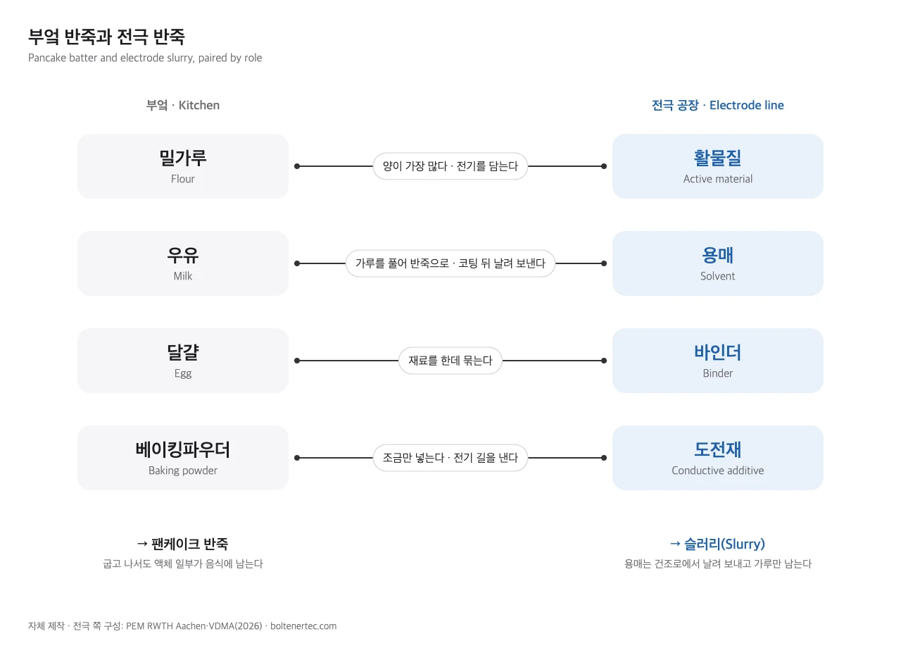
Think of pancake batter. Flour plays the active material, milk the solvent, and egg, which ties everything together, the binder. The conductive additive is like baking powder: you only add a little.
Milk stays in the pancake, though. The solvent in electrode slurry is driven off in the drying oven after coating, and toxic solvents are recovered and processed or recycled (PEM/VDMA). Only the powders remain in the electrode.
In Figure 2, I paired the kitchen and electrode ingredients by the job they do. Leave out the baking powder and the pancake stays flat. The conductive additive is also the smallest ingredient, yet without it the electrical conduction through the electrode drops sharply (Bockholt et al. 2016).
The quantities differ a lot. In the PEM/VDMA sample recipes, cathode powder is 95% active material, 1% carbon and 4% PVDF binder by weight. The anode is 95% graphite, 1% carbon, 2% CMC binder and 2% SBR additive. The liquid is NMP5 for the cathode and deionized water for the anode. Figure 3 lays out both powder recipes as 100 g spread over a 100-cell grid.
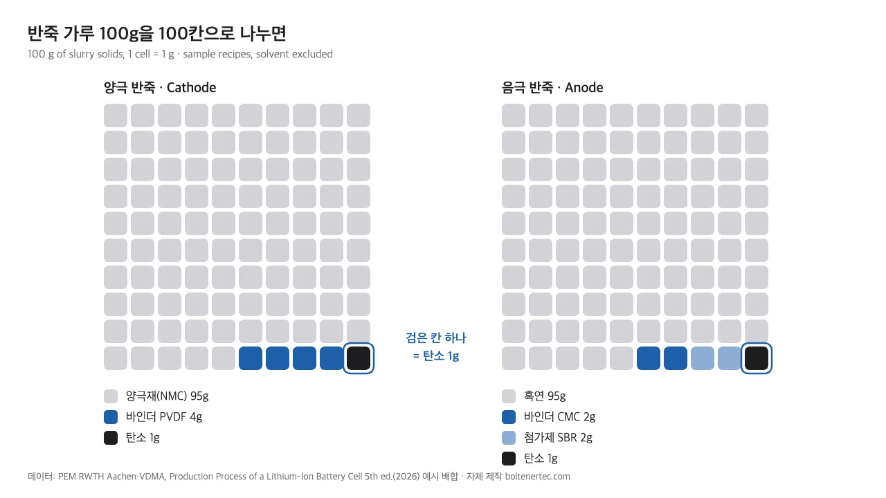
The cathode grid has exactly one black cell. That single gram has to bridge the active-material particles for current to flow through the whole electrode. In their introduction, Bockholt et al. (2016) summarize earlier work showing that uneven carbon leaves parts of the electrode unused, which cuts capacity and cycle life.
Inside the mixing vessel
PEM/VDMA break mixing into several steps. It starts with dosing the weighed powders into the vessel and mixing them dry to spread them evenly. Once the solvent goes in, the clumps are broken up and distributed through the liquid, a step called dispersion6.
The binder either goes in with the other powders at the start or is added later as a separate solution. At the end, a vacuum pulls out the air trapped in the paste. A baker taps the cake pan on the counter to knock out bubbles; the mixer does the same job with vacuum.
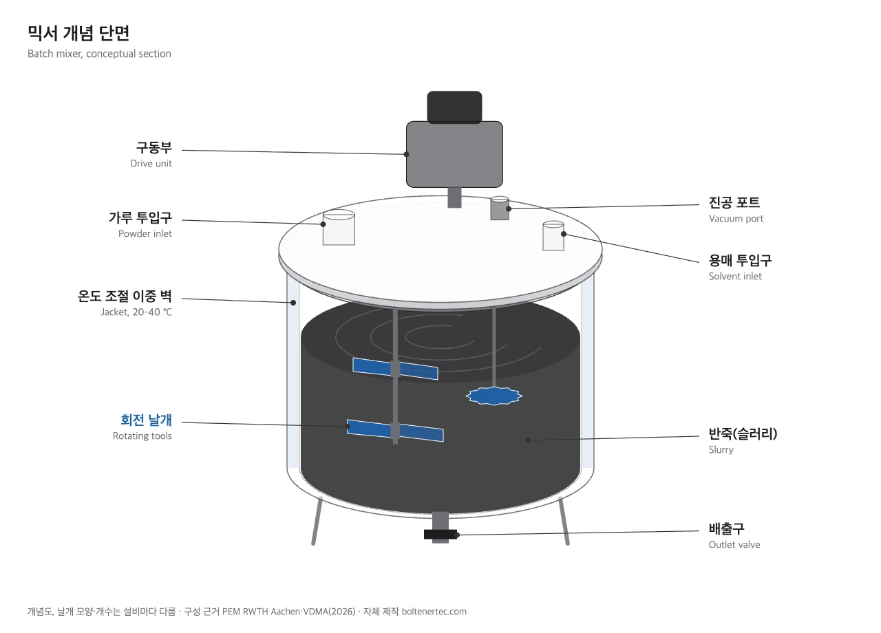
In Figure 4, the paste gets its energy from the rotating blades in the middle; at every stage, at least one of them is turning (PEM/VDMA). How many there are and what they look like depends on the mixer design. The table below collects the operating conditions and quality checks.
| Item | Condition per PEM/VDMA |
|---|---|
| Vessel temperature | Controlled at 20–40 °C |
| Atmosphere in the vessel | Inert gas or vacuum |
| Installation site | Clean room or no special requirement |
| Mixer assignment | Separate mixers for cathode and anode |
| Quality checks | Homogeneity, agglomerate size, bubbles, foreign matter, viscosity |
I’d start with mixer assignment: cathode and anode never share a mixer (PEM/VDMA). To avoid cross contamination7 between the two slurries, a plant buys the same machine twice.
Viscosity8, one of the quality checks, describes how thick the paste is. For someone like me who designs the rolls on a coater9, it is the first number that tells me how the paste will behave on the roll and the foil. The same paste thins or thickens with temperature, so I always read it together with the first row of the table.
Six hours is 18 times 20 minutes. Bockholt et al. (2016) note that the energy the powder receives depends on both mixing intensity and time, and that it differs from one type of mixer to another. The same recipe can need very different times depending on the machine and how hard it is run.
The equipment bill is not small either. For a 10 GWh pouch-cell plant, mixing equipment runs €30–55 million (PEM/VDMA), on par with the €35–65 million for coating and drying. Last issue’s total for 13 process steps was €280–505 million. Divide low end by low end and high end by high end, and mixing comes out at about 11% either way.
Is longer mixing always better?
Bakers say that overmixing muffin batter makes it tough. Battery slurry has no gluten to toughen. But overmixing can still damage the carbon, the smallest ingredient in the paste and the one that carries the current.
The longer and harder you mix, the finer the paste and the better the electrode.
There is a sweet spot. Too little mixing leaves the carbon unevenly spread; too much breaks up the carbon branches that carry current over long distances (Lian et al. 2025).
The usual conductive additive, carbon black10, is a powder of tiny carbon particles clumped into branching structures (Bockholt et al. 2016). Those branches reach across the active-material particles and form bridges that let current travel a long way. Overmixing breaks those bridges.
Lian et al. (2025) varied dry-mixing conditions and measured the electrical resistance of the powder. Undermixed powder had its carbon unevenly spread, while overmixed powder lost its carbon branches and its resistance went back up. The best settings also depended on how much carbon there was: fast and short worked for low carbon content, slow and long for high.
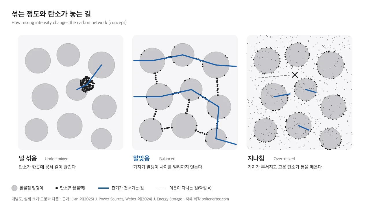
The powder with the lowest resistance did not make the best electrode. In Lian’s tests, the electrodes with the best rate performance and cycle life had a balanced mix of short- and long-range contacts. Those electrodes actually had higher powder resistance.
Weber et al. (2024) took the question into cells. The team used a twin-screw extruder11 to vary mixing intensity while making cathodes, then compared their capacity at a high C-rate12. At a 3C discharge, the electrode with the most finely dispersed carbon had the lowest capacity, and the least dispersed one came next.
The highest capacity came from dispersion levels in between, where ionic resistance was also lowest. The authors attribute this to the extra carbon surface created by finer dispersion, which blocks the paths ions travel through. Electrodes made inside their target range showed a 26% improvement in 3C discharge capacity.
Between them, the two studies show when to stop the mixer. The carbon should be evenly spread, the long branches still intact, and nothing ground so fine that it blocks the ion paths. I read the wide 20-minute-to-6-hour range as a sign that this point shifts with every material and every machine.
How a roll designer looks at a mixer
I started in mechanical design in 2005 and have mostly worked on roll-to-roll13 equipment since. The high-temperature coating rolls on the coater, the roll press14 that compacts the electrode, and the slitter that cuts it into strips all sit downstream of the mixer. So when I look at a mixer, I picture the moment its paste lands on my rolls.
Lay the PEM/VDMA quality lists side by side and the mixing checks (agglomerate size, bubbles, foreign matter) line up with the coating checks (voids and particles on the surface). I treat the two lists as a single set of design requirements.
Boltenertec · roll press, slitter and coating roll design
One result in Bockholt et al. (2016) caught my eye as a roll-press designer. Electrodes made from intensively dry-mixed powder lost long-range contacts and did worse at high rates. That loss showed up before calendering; once the electrodes went through the roll press, the contacts were re-established and the loss was made up.
I don’t take this to mean the roll can cover for the mixer. The roll restored broken carbon contacts, but it cannot remove foreign particles or bubbles that got into the paste. Those have to be caught at the mixer.
On the machine itself, I start with the load path. With a top-mounted drive as in Figure 4, the reaction force from the blades pushing on the paste travels up the shaft into the bearings, the lid and the frame. The thicker the paste, the more torque it takes to turn the blades. In my view, the stiffness of those parts decides how long the machine lasts.
For investors following industry news, mixing equipment deserves the same attention as coating and drying equipment. PEM/VDMA list continuous mixing with a twin-screw extruder among current technology alternatives, and dry, solvent-free mixing as an innovation trend. When either phrase appears in the news, it points to a change in how the slurry itself is made.
If you are preparing for a process engineering role, read the mixing page of the PEM/VDMA guide. Mixing time, temperature, vessel atmosphere and quality checks fit on a single page. The later steps, such as coating and calendering, follow the same format, so you can quickly see how the processes connect. The guide is available as a free PDF from VDMA.
One step further for engineers
A common way to compare mixing conditions is the specific energy input.
$$E_m = \frac{(P – P_0)\, t}{m}$$
$E_m$ is the energy put into each kilogram of paste (kJ/kg). $P$ is the mixing power during operation and $P_0$ the power drawn when the vessel runs empty, both in kW. $t$ is the mixing time (s) and $m$ the paste mass (kg).
Lian et al. (2025) also concluded that how far the carbon breaks up depends mainly on the total energy input, set largely by mixing time and speed. Researchers still measure the dispersion itself instead of stopping at an energy figure. Weber et al.’s carbon black dispersion index (DICB) and Lian et al.’s powder resistivity are two examples.
Further reading: Silicon anodes and CNT dry conductive additives · Dry electrode calendering: nip pressure and differential speed · How a VC roll works: hydraulic sleeve crown control
A mixer has to spread the 1 g of carbon in every 100 g of powder evenly without breaking it apart. Finding that point can take 20 minutes or 6 hours. The paste that comes out goes straight onto the coater’s rolls and from there onto the foil.
Glossary
- Slurry: a thick, flowing paste of solid powder in a liquid. PEM/VDMA use this name for the product of the mixing step. ↩
- Binder: the material that sticks active-material and conductive particles to each other and holds the coating on the metal foil. In the sample recipes, the cathode uses PVDF and the anode CMC. ↩
- Active material: the material that takes in and releases lithium ions during charge and discharge, storing the energy. The cathode uses a cathode active material, the anode a material such as graphite. ↩
- Conductive additive: a carbon material that creates paths for electrons inside the electrode. Only a little goes in, but it raises the coating’s electrical conductivity considerably. ↩
- NMP (N-methyl-2-pyrrolidone): the organic solvent used in cathode slurry. It is evaporated with heat in the drying section after coating. ↩
- Dispersion: breaking up clumps of powder and spreading them evenly through the liquid. PEM/VDMA call this step dispersive mixing. ↩
- Cross contamination: material from one side getting into the other and degrading quality. ↩
- Viscosity: a liquid’s resistance to flow. Honey has a higher viscosity than water. ↩
- Coater: the machine that applies slurry to metal foil at a set thickness and dries it in an oven, using an applicator such as a slot die (PEM/VDMA). ↩
- Carbon black: a black powder of nanoscale carbon particles clumped into branching structures, widely used as a conductive additive in electrodes. ↩
- Twin-screw extruder: a machine in which two intermeshing screws push material forward while mixing it. Instead of working in batches, it turns out paste continuously. ↩
- High C-rate: the C-rate expresses charge or discharge speed, and 1C empties a cell in one hour. A high C-rate is anything faster. ↩
- Roll-to-roll (R2R): a continuous production method in which a thin web is unwound from a roll, processed and wound up again. ↩
- Roll press: a machine that passes the electrode between an upper and a lower roll to compact the coating. The process is called calendering (PEM/VDMA). ↩
Sources
- PEM of RWTH Aachen University & VDMA, Production Process of a Lithium-Ion Battery Cell, 5th edition, February 2026, ISBN 978-3-947920-71-6. Pages: Dosing & Mixing, Coating & Drying, Factory Concept. VDMA download (PDF)
- Weber M., Gerstenberg J., Kwade A., Impact of CB dispersion on the performance of lithium-ion battery cathodes, Journal of Energy Storage 99, 113244, 2024, CC BY-NC 4.0. https://doi.org/10.1016/j.est.2024.113244
- Lian G.J., Verma P., Cumming D., Smith R.M., Probing carbon black deagglomeration in lithium-ion battery cathode manufacturing using powder resistivity metrics, Journal of Power Sources 659, 238311, 2025, CC BY-NC-ND 4.0. https://doi.org/10.1016/j.jpowsour.2025.238311
- Bockholt H., Haselrieder W., Kwade A., Intensive powder mixing for dry dispersing of carbon black and its relevance for lithium-ion battery cathodes, Powder Technology 297, 266–274, 2016. https://doi.org/10.1016/j.powtec.2016.04.011
- My calculation: mixing time ratio (360 min ÷ 20 min); mixing’s share of equipment investment against the sum of PEM/VDMA’s 13 pouch-cell process ranges, low and high ends taken separately.
This article is meant to help readers understand the industry and its technology. It is not a recommendation to buy or sell any stock.